Subaru Legacy (2005 year). Service manual — part 477
EN(H6DO)(diag)-221
ENGINE (DIAGNOSTICS)
Diagnostic Procedure with Diagnostic Trouble Code (DTC)
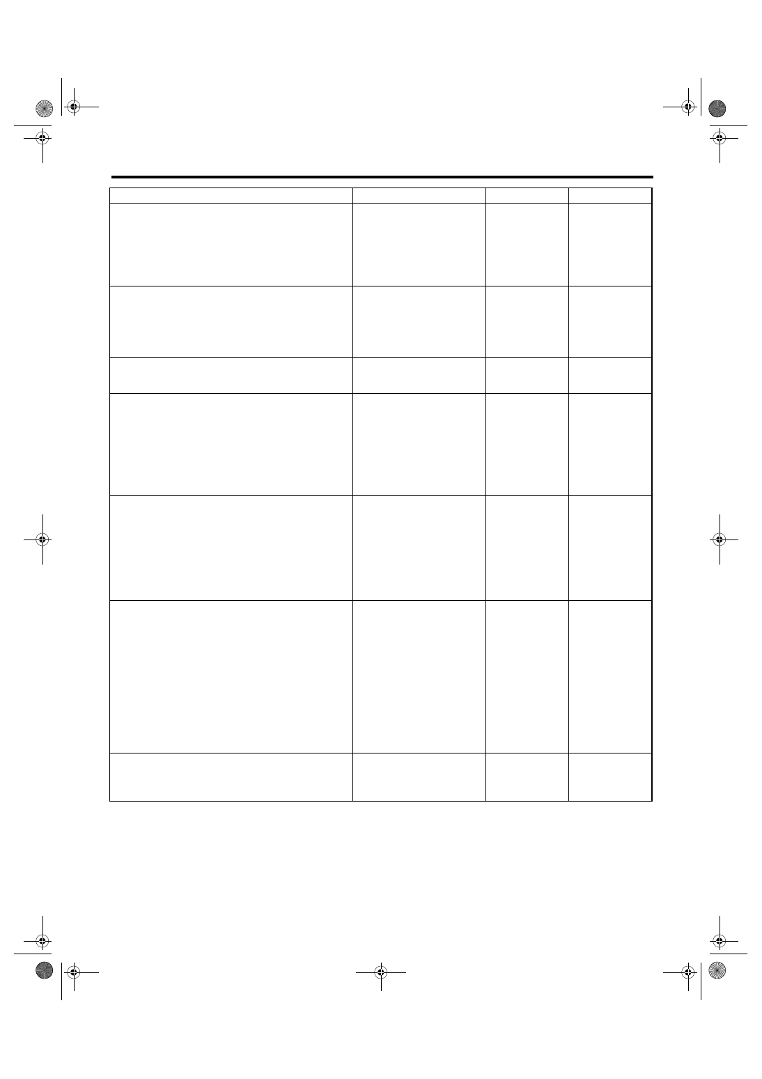
Step
Check
Yes
No
1
CHECK INPUT SIGNAL OF ECM.
1) Turn the ignition switch to ON.
2) Place the shift lever except in neutral.
3) Measure the voltage between ECM and
chassis ground.
Connector & terminal
(B137) No. 9 (+) — Chassis ground (
−
):
Is the voltage more than 10 V? Go to step 2.
2
CHECK INPUT SIGNAL OF ECM.
1) Place the shift lever in neutral.
2) Measure the voltage between ECM and
chassis ground.
Connector & terminal
(B137) No. 9 (+) — Chassis ground (
−
):
Is the voltage less than 1 V?
3
CHECK POOR CONTACT.
Check poor contact in ECM connector.
Is there poor contact in ECM
connector?
Repair the poor
contact in ECM
connector.
Replace the ECM.
4
CHECK NEUTRAL POSITION SWITCH.
1) Place the shift lever in neutral.
2) Measure the resistance between transmis-
sion harness connector terminals.
Connector & terminal
LHD model
(T2) No. 1 — No. 3:
LHD model
(T9) No. 1 — No. 3:
Is the resistance less than 1
Ω?
Repair the open
circuit in transmis-
sion harness or
replace the neu-
tral position switch.
5
CHECK HARNESS BETWEEN ECM AND
NEUTRAL POSITION SWITCH CONNEC-
TOR.
1) Disconnect the connector from ECM.
2) Measure the resistance of harness
between ECM and transmission harness con-
nector.
Connector & terminal
(B137) No. 9 — (B128) No. 1:
Is the resistance less than 1
Ω?
Repair the open
circuit of harness
between ECM and
transmission har-
ness connector.
6
CHECK HARNESS BETWEEN ECM AND
NEUTRAL POSITION SWITCH CONNEC-
TOR.
Measure the resistance of harness between
transmission harness connector and engine
ground.
Connector & terminal
(B128) No. 3 — Engine ground:
Is the resistance less than 5
Ω?
Repair the har-
ness and connec-
tor.
NOTE:
In this case, repair
the following:
• Open circuit of
harness between
transmission har-
ness connector
and engine ground
• Poor contact in
coupling connector
7
CHECK POOR CONTACT.
Check poor contact in transmission harness
connector.
Is there poor contact in trans-
mission harness connector?
Repair poor con-
tact in transmis-
sion harness
connector.
Replace the ECM.
EN(H6DO)(diag)-222
ENGINE (DIAGNOSTICS)
Diagnostic Procedure with Diagnostic Trouble Code (DTC)
CF:DTC P1160 RETURN SPRING FAILURE
NOTE:
For diagnostic procedure, refer to DTC P2101. <Ref. to EN(H6DO)(diag)-239, DTC P2101 THROTTLE AC-
TUATOR CONTROL MOTOR CIRCUIT RANGE/PERFORMANCE, Diagnostic Procedure with Diagnostic
Trouble Code (DTC).>
CG:DTC P1492 EGR SOLENOID VALVE SIGNAL #1 CIRCUIT MALFUNCTION
(LOW INPUT)
NOTE:
For the diagnostic procedure, refer to DTC P1498. <Ref. to EN(H6DO)(diag)-223, DTC P1498 EGR SOLE-
NOID VALVE SIGNAL #4 CIRCUIT MALFUNCTION (LOW INPUT), Diagnostic Procedure with Diagnostic
Trouble Code (DTC).>
CH:DTC P1493 EGR SOLENOID VALVE SIGNAL #1 CIRCUIT MALFUNCTION
(HIGH INPUT)
NOTE:
For the diagnostic procedure, refer to DTC P1499. <Ref. to EN(H6DO)(diag)-225, DTC P1499 EGR SOLE-
NOID VALVE SIGNAL #4 CIRCUIT MALFUNCTION (HIGH INPUT), Diagnostic Procedure with Diagnostic
Trouble Code (DTC).>
CI: DTC P1494 EGR SOLENOID VALVE SIGNAL #2 CIRCUIT MALFUNCTION
(LOW INPUT)
NOTE:
For the diagnostic procedure, refer to DTC P1498. <Ref. to EN(H6DO)(diag)-223, DTC P1498 EGR SOLE-
NOID VALVE SIGNAL #4 CIRCUIT MALFUNCTION (LOW INPUT), Diagnostic Procedure with Diagnostic
Trouble Code (DTC).>
CJ:DTC P1495 EGR SOLENOID VALVE SIGNAL #2 CIRCUIT MALFUNCTION
(HIGH INPUT)
NOTE:
For the diagnostic procedure, refer to DTC P1499. <Ref. to EN(H6DO)(diag)-225, DTC P1499 EGR SOLE-
NOID VALVE SIGNAL #4 CIRCUIT MALFUNCTION (HIGH INPUT), Diagnostic Procedure with Diagnostic
Trouble Code (DTC).>
CK:DTC P1496 EGR SOLENOID VALVE SIGNAL #3 CIRCUIT MALFUNCTION
(LOW INPUT)
NOTE:
For the diagnostic procedure, refer to DTC P1498. <Ref. to EN(H6DO)(diag)-223, DTC P1498 EGR SOLE-
NOID VALVE SIGNAL #4 CIRCUIT MALFUNCTION (LOW INPUT), Diagnostic Procedure with Diagnostic
Trouble Code (DTC).>
CL:DTC P1497 EGR SOLENOID VALVE SIGNAL #3 CIRCUIT MALFUNCTION
(HIGH INPUT)
NOTE:
For the diagnostic procedure, refer to DTC P1499. <Ref. to EN(H6DO)(diag)-225, DTC P1499 EGR SOLE-
NOID VALVE SIGNAL #4 CIRCUIT MALFUNCTION (HIGH INPUT), Diagnostic Procedure with Diagnostic
Trouble Code (DTC).>
EN(H6DO)(diag)-223
ENGINE (DIAGNOSTICS)
Diagnostic Procedure with Diagnostic Trouble Code (DTC)
CM:DTC P1498 EGR SOLENOID VALVE SIGNAL #4 CIRCUIT MALFUNCTION
(LOW INPUT)
DTC DETECTING CONDITION:
Immediately at fault recognition
TROUBLE SYMPTOM:
• Erroneous idling
• Poor driving performance
• Engine breathing
CAUTION:
After repair or replacement of faulty parts, conduct Clear Memory Mode <Ref. to EN(H6DO)(diag)-41,
OPERATION, Clear Memory Mode.> and Inspection Mode <Ref. to EN(H6DO)(diag)-34, PROCEDURE,
Inspection Mode.>.
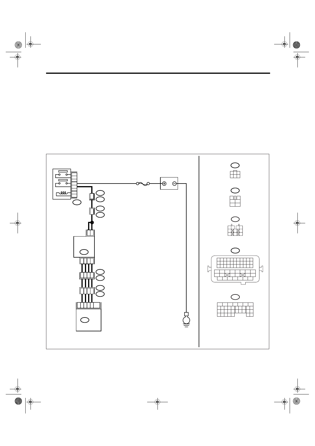
WIRING DIAGRAM:
EN-03502
E
B47
E18
2
5
1
4
3
6
B21
E2
E76
E77
48
3
10
9
11
8
4
7
6
SBF-7
BATTERY
MAIN RELAY
EGR
VALVE
B134
ECM
B47
3
4
1
2
5
6
B21
1 2 3 4
12 13 14 15
5 6 7 8
16 17 18 19
9 10 11
20 21 22
23 24 25 26 27 28 29 30 31 32 33
35
34
37
36
39
38
41
40
43
42
44
45
47
46
49
48
51
50
53
52
54
5
6
7
8
2
1
9
4
3
10
24
22 23
25
11 12 13 14 15
26 27
28
16 17
18 19 20 21
33 34
29
32
30 31
B134
10
E76
E77
21
32
33
22
B21
E2
E18
1
3
4 5 6
2
1 2
3 4
5
6
7
8
9
10
E77
6
4
EN(H6DO)(diag)-224
ENGINE (DIAGNOSTICS)
Diagnostic Procedure with Diagnostic Trouble Code (DTC)
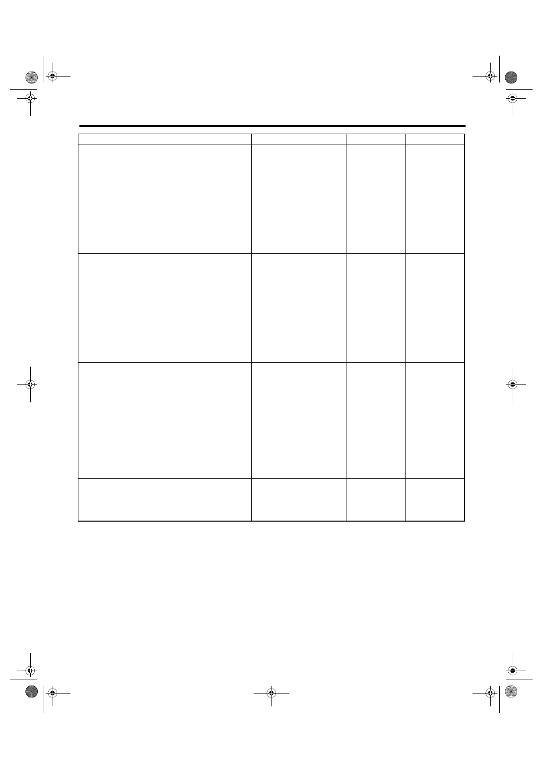
Step
Check
Yes
No
1
CHECK POWER SUPPLY TO EGR SOLE-
NOID VALVE.
1) Turn the ignition switch to OFF.
2) Disconnect the connector from EGR sole-
noid valve.
3) Turn the ignition switch to ON.
4) Measure the voltage between EGR sole-
noid valve connector and engine ground.
Connector & terminal
(E18) No. 2 (+) — Engine ground (
−
):
(E18) No. 5 (+) — Engine ground (
−
):
Is the voltage more than 10 V? Go to step 2.
Repair the har-
ness and connec-
tor.
NOTE:
In this case, repair
the following:
• Open circuit of
harness between
EGR solenoid
valve and main
relay connector
• Poor contact in
coupling connector
2
CHECK HARNESS BETWEEN ECM AND
EGR SOLENOID VALVE CONNECTOR.
1) Turn the ignition switch to OFF.
2) Measure the resistance between ECM and
EGR solenoid valve connector.
Connector & terminal
DTC P1492; (B134) No. 11 — (E18) No. 3:
DTC P1494; (B134) No. 10 — (E18) No. 1:
DTC P1496; (B134) No. 9 — (E18) No. 4:
DTC P1498; (B134) No. 8 — (E18) No. 6:
Is the resistance less than 1
Ω?
Repair the har-
ness and connec-
tor.
NOTE:
In this case, repair
the following:
• Open circuit of
harness between
ECM and EGR
solenoid valve
connector
• Poor contact in
coupling connector
3
CHECK HARNESS BETWEEN ECM AND
EGR SOLENOID VALVE CONNECTOR.
1) Disconnect the connector from ECM.
2) Measure the resistance between ECM con-
nector and chassis ground.
Connector & terminal
DTC P1492; (B134) No. 11 — Chassis
ground:
DTC P1494; (B134) No. 10 — Chassis
ground:
DTC P1496; (B134) No. 9 — Chassis
ground:
DTC P1498; (B134) No. 8 — Chassis
ground:
Is the resistance more than 1
M
Ω?
Repair the ground
short in harness
between ECM and
EGR solenoid
valve connector.
4
CHECK POOR CONTACT.
Check poor contact in ECM connector and
EGR solenoid valve connector.
Is there poor contact in ECM
connector or EGR solenoid
valve connector?
Repair the poor
contact in ECM
connector or EGR
solenoid valve
connector.
Replace the EGR
solenoid valve.
<Ref. to
FU(H6DO)-25,
EGR Valve.>
Нет комментариевНе стесняйтесь поделиться с нами вашим ценным мнением.
Текст