Subaru Legacy (2005 year). Service manual — part 478
EN(H6DO)(diag)-225
ENGINE (DIAGNOSTICS)
Diagnostic Procedure with Diagnostic Trouble Code (DTC)
CN:DTC P1499 EGR SOLENOID VALVE SIGNAL #4 CIRCUIT MALFUNCTION
(HIGH INPUT)
DTC DETECTING CONDITION:
Immediately at fault recognition
TROUBLE SYMPTOM:
• Erroneous idling
• Poor driving performance
• Engine breathing
CAUTION:
After repair or replacement of faulty parts, conduct Clear Memory Mode <Ref. to EN(H6DO)(diag)-41,
OPERATION, Clear Memory Mode.> and Inspection Mode <Ref. to EN(H6DO)(diag)-34, PROCEDURE,
Inspection Mode.>.
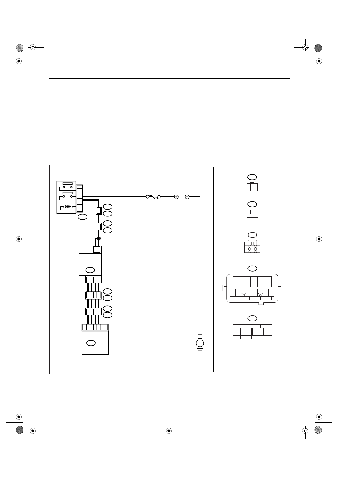
WIRING DIAGRAM:
EN-03502
E
B47
E18
2
5
1
4
3
6
B21
E2
E76
E77
48
3
10
9
11
8
4
7
6
SBF-7
BATTERY
MAIN RELAY
EGR
VALVE
B134
ECM
B47
3
4
1
2
5
6
B21
1 2 3 4
12 13 14 15
5 6 7 8
16 17 18 19
9 10 11
20 21 22
23 24 25 26 27 28 29 30 31 32 33
35
34
37
36
39
38
41
40
43
42
44
45
47
46
49
48
51
50
53
52
54
5
6
7
8
2
1
9
4
3
10
24
22 23
25
11 12 13 14 15
26 27
28
16 17
18 19 20 21
33 34
29
32
30 31
B134
10
E76
E77
21
32
33
22
B21
E2
E18
1
3
4 5 6
2
1 2
3 4
5
6
7
8
9
10
E77
6
4
EN(H6DO)(diag)-226
ENGINE (DIAGNOSTICS)
Diagnostic Procedure with Diagnostic Trouble Code (DTC)
CO:DTC P1518 STARTER SWITCH CIRCUIT LOW INPUT
DTC DETECTING CONDITION:
Detects when malfunction occurs in 2 continuous driving cycles.
TROUBLE SYMPTOM:
Failure of engine to start
CAUTION:
After repair or replacement of faulty parts, conduct Clear Memory Mode <Ref. to EN(H6DO)(diag)-41,
OPERATION, Clear Memory Mode.> and Inspection Mode <Ref. to EN(H6DO)(diag)-34, PROCEDURE,
Inspection Mode.>.
Step
Check
Yes
No
1
CHECK ANY OTHER DTC ON DISPLAY.
Is any other DTC displayed?
Check DTC using
the List of Diag-
nostic Trouble
Code (DTC). <Ref.
to
EN(H6DO)(diag)-
66, List of Diag-
nostic Trouble
Code (DTC).>
2
CHECK HARNESS BETWEEN ECM AND
EGR SOLENOID VALVE CONNECTOR.
1) Turn the ignition switch to OFF.
2) Disconnect the connector from EGR sole-
noid valve.
3) Turn the ignition switch to ON.
4) Measure the voltage between ECM con-
nector and chassis ground.
Connector & terminal
DTC P1493; (B134) No. 11 (+) — Chassis
ground (
−
):
DTC P1495; (B134) No. 10 (+) — Chassis
ground (
−
):
DTC P1497; (B134) No. 9 (+) — Chassis
ground (
−
):
DTC P1499; (B134) No. 8 (+) — Chassis
ground (
−
):
Is the voltage more than 10 V? Repair the battery
short in harness
between ECM and
EGR solenoid
valve connector.
After repair,
replace the ECM.
<Ref. to
FU(H6DO)-34,
Engine Control
Module (ECM).>
Replace the ECM.
<Ref. to
FU(H6DO)-34,
Engine Control
Module (ECM).>
EN(H6DO)(diag)-227
ENGINE (DIAGNOSTICS)
Diagnostic Procedure with Diagnostic Trouble Code (DTC)
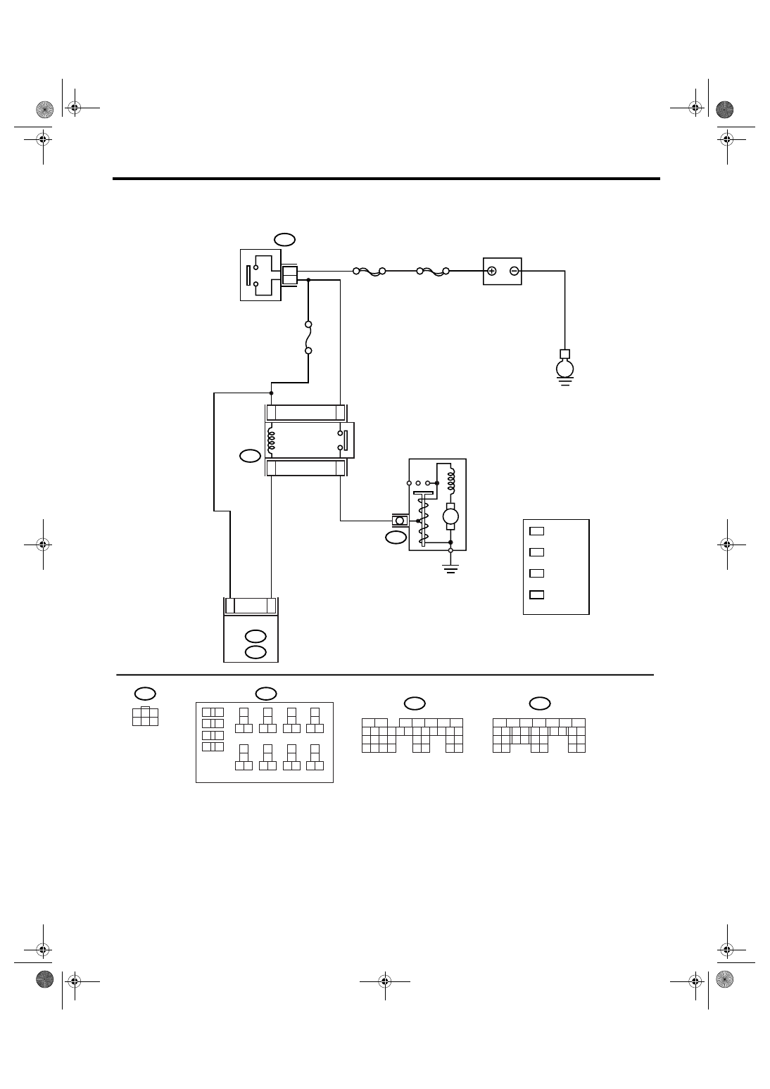
WIRING DIAGRAM:
EN-03489
D8
B32
No.21
B225
MAIN SBF
SBF-6
E
1
3
2
4
ECM
B137
D:
B135
B:
B72
B14
M
2
3
B225
B137
B72
D:
B135
B:
10
11 12
13
14
15 16
17
18
19 20
21
22
23 24
25
26
27 28
29
30
31 32
33
34
35 36
39 40
37
38
1
2
9
3
4
5
6
7
8
1
2
7
8 9
5
6
3
4
10 11 12
19 20 21
29
30 31
13 14 15 16 17
27
28
18
22 23
24 25
26
1
2
7
8 9
5
6
3
4
10 11 12
19
20 21
29 30 31
13 14 15 16 17
27
28
18
22 23
24 25
26
32 33
34 35
1
3
4 5 6
2
BATTERY
IGNITION
SWITCH
STARTER
RELAY
STARTER MOTOR
*
*
*
*
*
LHD: 15
RHD: 16
1
*
LHD: 16
RHD: 15
2
*
LHD: 13
RHD: 14
3
*
LHD: 14
RHD: 13
4
EN(H6DO)(diag)-228
ENGINE (DIAGNOSTICS)
Diagnostic Procedure with Diagnostic Trouble Code (DTC)
Step
Check
Yes
No
1
CHECK OPERATION OF STARTER MOTOR.
Turn the ignition switch to START.
NOTE:
• For AT model, place the select lever in “P” or
“N” range.
• For MT model, depress the clutch pedal.
Does the starter motor oper-
ate?
Repair the har-
ness and connec-
tor.
NOTE:
In this case, repair
the following:
• Open or ground
short circuit of har-
ness between
ECM and starter
motor connector
• Poor contact in
ECM connector
Check the starter
motor circuit. <Ref.
to
EN(H6DO)(diag)-
54, STARTER
MOTOR CIRCUIT,
Diagnostics for
Engine Starting
Failure.>
Нет комментариевНе стесняйтесь поделиться с нами вашим ценным мнением.
Текст