Subaru Legacy (2005 year). Service manual — part 476

EN(H6DO)(diag)-217
ENGINE (DIAGNOSTICS)
Diagnostic Procedure with Diagnostic Trouble Code (DTC)
CD:DTC P0851 PARK/NEUTRAL SWITCH INPUT CIRCUIT LOW
DTC DETECTING CONDITION:
Detects when malfunction occurs in 2 continuous driving cycles.
TROUBLE SYMPTOM:
Erroneous idling
CAUTION:
After repair or replacement of faulty parts, conduct Clear Memory Mode <Ref. to EN(H6DO)(diag)-41,
OPERATION, Clear Memory Mode.> and Inspection Mode <Ref. to EN(H6DO)(diag)-34, PROCEDURE,
Inspection Mode.>.
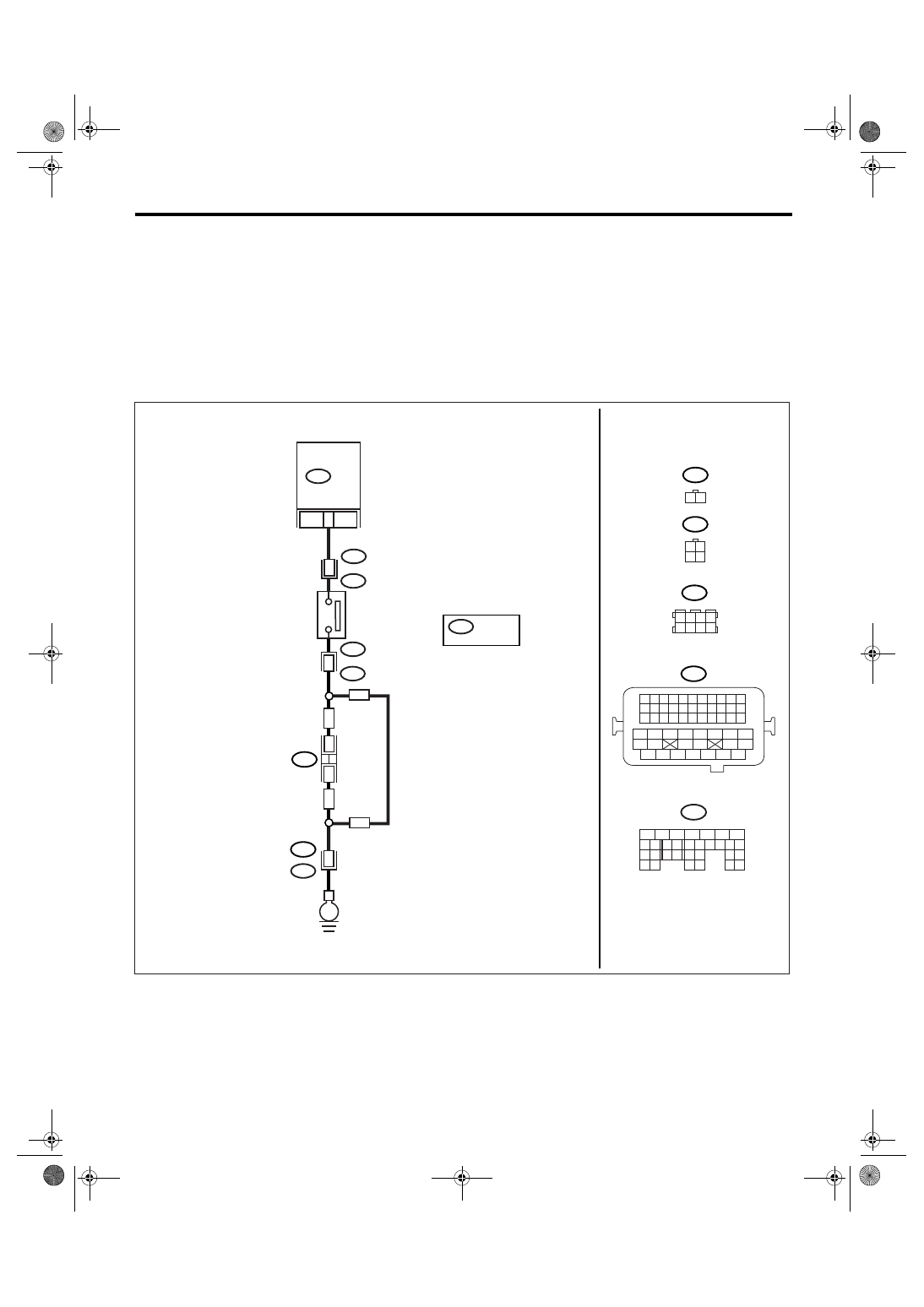
WIRING DIAGRAM:
EN-03505
1
B128
3
B137
9
B128
E2
1 2
B25
E
NEUTRAL
POSITION
SWITCH
ECM
B137
5
6
7
8
2
1
9
4
3
10
22 23
11 12 13 14 15
24 25
26
16 17
18 19 20 21
27
28 29
30 31
B21
B21
1 2 3 4
12 13 14 15
5 6 7 8
16 17 18 19
9 10 11
20 21 22
23 24 25 26 27 28 29 30 31 32 33
35
34
37
36
39
38
41
40
43
42
44
45
47
46
49
48
51
50
53
52
54
B138
B138
1 2 3 4
5 6 7 8
1 2
3 4
B128
LHD
LHD
RHD
RHD
*
*
*
36
LHD : T2
RHD : T9
*
*
EN(H6DO)(diag)-218
ENGINE (DIAGNOSTICS)
Diagnostic Procedure with Diagnostic Trouble Code (DTC)
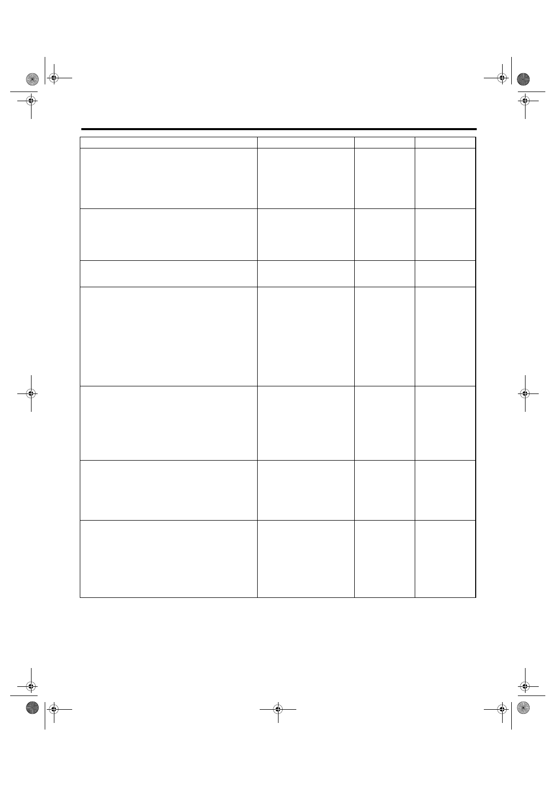
Step
Check
Yes
No
1
CHECK INPUT SIGNAL OF ECM.
1) Turn the ignition switch to ON.
2) Place the shift lever in neutral.
3) Measure the voltage between ECM and
chassis ground.
Connector & terminal
(B137) No. 9 (+) — Chassis ground (
−
):
Is the voltage less than 1 V?
2
CHECK INPUT SIGNAL OF ECM.
1) Place the shift lever except in neutral.
2) Measure the voltage between ECM and
chassis ground.
Connector & terminal
(B137) No. 9 (+) — Chassis ground (
−
):
Is the voltage more than 10 V? Go to step 3.
3
CHECK POOR CONTACT.
Check poor contact in ECM connector.
Is there poor contact in ECM
connector?
Repair the poor
contact in ECM
connector.
Replace the ECM.
4
CHECK NEUTRAL POSITION SWITCH.
1) Turn the ignition switch to OFF.
2) Disconnect the connector from transmis-
sion harness.
3) Place the shift lever in neutral.
4) Measure the resistance between transmis-
sion harness and connector terminals.
Connector & terminal
LHD model
(T2) No. 1 — No. 3:
RHD model
(T9) No. 1 — No. 3:
Is the resistance less than 1
Ω?
Repair short circuit
in transmission
harness or replace
the neutral position
switch.
5
CHECK NEUTRAL POSITION SWITCH.
1) Place the shift lever except in neutral.
2) Measure the resistance between transmis-
sion harness connector terminals.
Connector & terminal
LHD model
(T2) No. 1 — No. 3:
RHD model
(T9) No. 1 — No. 3:
Is the resistance more than 1
M
Ω?
Repair short circuit
in transmission
harness or replace
the neutral position
switch.
6
CHECK HARNESS BETWEEN ECM AND
NEUTRAL POSITION SWITCH CONNEC-
TOR.
Measure the resistance between ECM and
chassis ground.
Connector & terminal
(B137) No. 9 — Chassis ground:
Is the resistance more than 1
M
Ω?
Repair the ground
short circuit of har-
ness between
ECM and trans-
mission harness
connector.
7
CHECK HARNESS BETWEEN ECM AND
NEUTRAL POSITION SWITCH CONNEC-
TOR.
1) Disconnect the connector from ECM.
2) Measure the resistance of harness
between ECM and transmission harness con-
nector.
Connector & terminal
(B137) No. 9 — (B128) No. 1:
Is the resistance less than 1
Ω?
Repair the open
circuit of harness
between ECM and
transmission har-
ness connector.
EN(H6DO)(diag)-219
ENGINE (DIAGNOSTICS)
Diagnostic Procedure with Diagnostic Trouble Code (DTC)
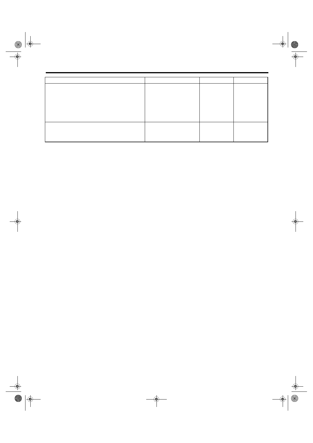
8
CHECK HARNESS BETWEEN ECM AND
NEUTRAL POSITION SWITCH CONNEC-
TOR.
Measure the resistance of harness between
transmission harness connector and engine
ground.
Connector & terminal
(B128) No. 3 — Engine ground:
Is the resistance less than 5
Ω?
Repair the open
circuit between
transmission har-
ness connector
and engine ground
terminal.
9
CHECK POOR CONTACT.
Check poor contact in transmission harness
connector.
Is there poor contact in trans-
mission harness connector?
Repair poor con-
tact in transmis-
sion harness
connector.
Replace the ECM.
Step
Check
Yes
No
EN(H6DO)(diag)-220
ENGINE (DIAGNOSTICS)
Diagnostic Procedure with Diagnostic Trouble Code (DTC)
CE:DTC P0852 PARK/NEUTRAL SWITCH INPUT CIRCUIT HIGH
DTC DETECTING CONDITION:
Detects when malfunction occurs in 2 continuous driving cycles.
TROUBLE SYMPTOM:
Erroneous idling
CAUTION:
After repair or replacement of faulty parts, conduct Clear Memory Mode <Ref. to EN(H6DO)(diag)-41,
OPERATION, Clear Memory Mode.> and Inspection Mode <Ref. to EN(H6DO)(diag)-34, PROCEDURE,
Inspection Mode.>.
WIRING DIAGRAM:
EN-03505
1
B128
3
B137
9
B128
E2
1 2
B25
E
NEUTRAL
POSITION
SWITCH
ECM
B137
5
6
7
8
2
1
9
4
3
10
22 23
11 12 13 14 15
24 25
26
16 17
18 19 20 21
27
28 29
30 31
B21
B21
1 2 3 4
12 13 14 15
5 6 7 8
16 17 18 19
9 10 11
20 21 22
23 24 25 26 27 28 29 30 31 32 33
35
34
37
36
39
38
41
40
43
42
44
45
47
46
49
48
51
50
53
52
54
B138
B138
1 2 3 4
5 6 7 8
1 2
3 4
B128
LHD
LHD
RHD
RHD
*
*
*
36
LHD : T2
RHD : T9
*
*
Нет комментариевНе стесняйтесь поделиться с нами вашим ценным мнением.
Текст