Subaru Legacy (2005 year). Service manual — part 475

EN(H6DO)(diag)-213
ENGINE (DIAGNOSTICS)
Diagnostic Procedure with Diagnostic Trouble Code (DTC)
BX:DTC P0605 INTERNAL CONTROL MODULE READ ONLY MEMORY (ROM)
ERROR
NOTE:
For the diagnostic procedure, refer to DTC P0607. <Ref. to EN(H6DO)(diag)-214, DTC P0607 CONTROL
MODULE PERFORMANCE, Diagnostic Procedure with Diagnostic Trouble Code (DTC).>
Step
Check
Yes
No
1
CHECK ANY OTHER DTC ON DISPLAY.
Is any other DTC displayed?
Inspect the rele-
vant DTC using
“List of Diagnostic
Trouble Code
(DTC)”. <Ref. to
EN(H6DO)(diag)-
66, List of Diag-
nostic Trouble
Code (DTC).>
Temporary poor
contact occurs.
EN(H6DO)(diag)-214
ENGINE (DIAGNOSTICS)
Diagnostic Procedure with Diagnostic Trouble Code (DTC)
BY:DTC P0607 CONTROL MODULE PERFORMANCE
DTC DETECTING CONDITION:
Immediately at fault recognition
TROUBLE SYMPTOM:
• Erroneous idling
• Poor driving performance
CAUTION:
After repair or replacement of faulty parts, conduct Clear Memory Mode <Ref. to EN(H6DO)(diag)-41,
OPERATION, Clear Memory Mode.> and Inspection Mode <Ref. to EN(H6DO)(diag)-34, PROCEDURE,
Inspection Mode.>.
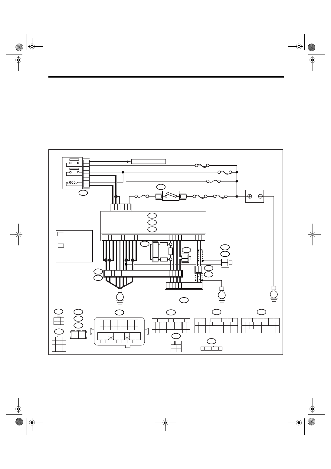
WIRING DIAGRAM:
EN-03504
BATTERY
IGNITION
SWITCH
MAIN RELAY
SBF-6
MAIN SBF
SBF-7
B72
B6
B5
D16
B19
D14
No.12
B47
E2
B21
E
3
6
3
4
1
2
5
6
B47
No.13
B134
5
6
7
8
2
1
9
4
3
10
24
22 23
25
11 12 13 14 15
26 27
28
16 17
18 19 20 21
33 34
29
32
30 31
B135
5
6
7
8
2
1
9
4
3
10
24
22 23
25
11 12 13 14 15
26 27
28
16 17 18 19
20 21
29 30 31
32 33
34 35
B137
5
6
7
8
2
1
9
4
3
10
22 23
11 12 13 14 15
24 25
26
16 17
18 19 20 21
27
28 29
30 31
B21
1 2 3 4
12 13 14 15
5 6 7 8
16 17 18 19
9 10 11
20 21 22
23 24 25 26 27 28 29 30 31 32 33
35
34
37
36
39
38
41
40
43
42
44
45
47
46
49
48
51
50
53
52
54
B72
1
3
4 5 6
2
A:
B:
D:
SBF-5
*
1
1
2
3
4
5
6
E57
1 2 3 4 5 6
B20
1 2 3 4
5 6 7 8
9 10 11 12
14
13
15 16
B122
3 4
5 6
1 2
7 8
B83
B138
E57
E1
B20
B122
B83
A6
D2
A7
B12
D3
D7
D1
ECM
B134
B135
A:
D: B137
B:
B4
*
*
B1
A4
A5
E
52
37
36
34
12
35
20
39
38
19
C16
D4
D5
C35
5
1
2
3
4
6
C29
C18
54
15
16
ELECTRONIC
THROTTLE CONTROL
1
1
E
RHD
RHD
LHD
*
*
B138
1
1
: TERMINAL No.
RANDOM
ARRANGEMEN
T
TO OXYGEN SENSOR
*
: TERMINAL No.
RANDOM
ARRANGEMENT
AMONG 3,4,7,
AND 8
2
*
2
*
2
B122 : LHD
: RHD
EN(H6DO)(diag)-215
ENGINE (DIAGNOSTICS)
Diagnostic Procedure with Diagnostic Trouble Code (DTC)
BZ:DTC P0638 THROTTLE ACTUATOR CONTROL RANGE/PERFORMANCE
(BANK 1)
NOTE:
For diagnostic procedure, refer to DTC P2101. <Ref. to EN(H6DO)(diag)-239, DTC P2101 THROTTLE AC-
TUATOR CONTROL MOTOR CIRCUIT RANGE/PERFORMANCE, Diagnostic Procedure with Diagnostic
Trouble Code (DTC).>
Step
Check
Yes
No
1
CHECK INPUT VOLTAGE OF ECM.
1) Turn the ignition switch to ON.
2) Measure the voltage between ECM con-
nector and chassis ground.
Connector & terminal
(B135) No. 5 (+) — Chassis ground (
−
):
(B135) No. 6 (+) — Chassis ground (
−
):
Is the voltage 10 — 13 V?
Repair the open or
ground short cir-
cuit of power sup-
ply circuit.
2
CHECK INPUT VOLTAGE OF ECM.
1) Start the engine.
2) Measure the voltage between ECM con-
nector and chassis ground.
Connector & terminal
(B135) No. 5 (+) — Chassis ground (
−
):
(B135) No. 6 (+) — Chassis ground (
−
):
Is the voltage 13 — 15 V?
Repair the open or
ground short cir-
cuit of power sup-
ply circuit.
3
CHECK HARNESS BETWEEN ECM AND
ELECTRONIC THROTTLE CONTROL.
1) Turn the ignition switch to OFF.
2) Disconnect the connectors from ECM and
electronic throttle control.
3) Measure the resistance of harness
between ECM and electronic throttle control
connector.
Connector & terminal
(E57) No. 5 — (B136) No. 16:
(E57) No. 3 — (B136) No. 35:
Is the resistance less than 1
Ω?
Repair the open
circuit of harness
between ECM and
electronic throttle
relay.
4
CHECK ECM GROUND HARNESS.
Measure the voltage between ECM connector
and chassis ground.
Connector & terminal
(B137) No. 1 (+) — Chassis ground (
−
):
(B137) No. 2 (+) — Chassis ground (
−
):
(B137) No. 3 (+) — Chassis ground (
−
):
Is the voltage less than 1 V?
Repair the poor
contact in ECM
connector.
Replace the ECM
if defective. <Ref.
to FU(H6DO)-34,
Engine Control
Module (ECM).>
Further tighten the
engine ground ter-
minal.
EN(H6DO)(diag)-216
ENGINE (DIAGNOSTICS)
Diagnostic Procedure with Diagnostic Trouble Code (DTC)
CA:DTC P0691 FAN 1 CONTROL CIRCUIT LOW
DTC DETECTING CONDITION:
Detects when malfunction occurs in 2 continuous driving cycles.
TROUBLE SYMPTOM:
• Radiator fan does not operate properly.
• Overheating
CAUTION:
After repair or replacement of faulty parts, conduct Clear Memory Mode <Ref. to EN(H6DO)(diag)-41,
OPERATION, Clear Memory Mode.> and Inspection Mode <Ref. to EN(H6DO)(diag)-34, PROCEDURE,
Inspection Mode.>.
CB:DTC P0692 FAN 1 CONTROL CIRCUIT HIGH
DTC DETECTING CONDITION:
Detects when malfunction occurs in 2 continuous driving cycles.
TROUBLE SYMPTOM:
• Radiator fan does not operate properly.
• Overheating
CAUTION:
After repair or replacement of faulty parts, conduct Clear Memory Mode <Ref. to EN(H6DO)(diag)-41,
OPERATION, Clear Memory Mode.> and Inspection Mode <Ref. to EN(H6DO)(diag)-34, PROCEDURE,
Inspection Mode.>.
CC:DTC P0700 TRANSMISSION CONTROL SYSTEM (MIL REQUEST)
NOTE:
For the diagnostic procedure, refer to AT section. <Ref. to 4AT(diag)-2, Basic Diagnostic Procedure.>
Step
Check
Yes
No
1
CHECK ANY OTHER DTC ON DISPLAY.
Is DTC P0691 displayed?
Check the radiator
fan system. <Ref.
to CO(H6DO)-8,
Radiator Fan Sys-
tem.>
Temporary poor
contact occurs.
Step
Check
Yes
No
1
CHECK ANY OTHER DTC ON DISPLAY.
Is DTC 692 displayed?
Check the radiator
fan system. <Ref.
to CO(H6DO)-8,
Radiator Fan Sys-
tem.>
Temporary poor
contact occurs.
Нет комментариевНе стесняйтесь поделиться с нами вашим ценным мнением.
Текст