Subaru Legacy (2005 year). Service manual — part 686
6MT-91
MANUAL TRANSMISSION AND DIFFERENTIAL
Reverse Idler Gear
21.Reverse Idler Gear
A: REMOVAL
1) Remove the manual transmission assembly
from vehicle. <Ref. to 6MT-34, REMOVAL, Manual
Transmission Assembly.>
2) Prepare the transmission for overhaul. <Ref. to
6MT-40, Preparation for Overhaul.>
3) Remove the oil pipe, neutral position switch,
back-up light switch and harness. <Ref. to 6MT-42,
REMOVAL, Oil Pipe.> <Ref. to 6MT-45, REMOV-
AL, Neutral Position Switch.> <Ref. to 6MT-43, RE-
MOVAL, Back-up Light Switch.>
4) Remove the extension case. <Ref. to 6MT-47,
REMOVAL, Extension Case.>
5) Remove the transfer driven gear. <Ref. to 6MT-
58, REMOVAL, Transfer Driven Gear.>
6) Remove the center differential. <Ref. to 6MT-60,
REMOVAL, Center Differential.>
7) Remove the oil pump. <Ref. to 6MT-61, RE-
MOVAL, Oil Pump.>
8) Remove the transmission case. <Ref. to 6MT-
64, REMOVAL, Transmission Case.>
9) Remove the reverse idler gear assembly. <Ref.
to 6MT-69, REMOVAL, Main Shaft Assembly.>
B: INSTALLATION
1) Select the reverse fork rod. <Ref. to 6MT-115,
ADJUSTMENT, Shifter Fork and Rod.>
2) Install the reverse idler gear assembly. <Ref. to
6MT-70, INSTALLATION, Main Shaft Assembly.>
3) Install the transmission case. <Ref. to 6MT-65,
INSTALLATION, Transmission Case.>
4) Install the oil pump. <Ref. to 6MT-62, INSTAL-
LATION, Oil Pump.>
5) Install the center differential. <Ref. to 6MT-60,
INSTALLATION, Center Differential.>
6) Install the transfer driven gear. <Ref. to 6MT-58,
INSTALLATION, Transfer Driven Gear.>
7) Install the extension case. <Ref. to 6MT-47, IN-
STALLATION, Extension Case.>
8) Install the oil pipe, neutral position switch, back-
up light switch and harness. <Ref. to 6MT-42, IN-
STALLATION, Oil Pipe.> <Ref. to 6MT-45, IN-
STALLATION, Neutral Position Switch.> <Ref. to
6MT-43, INSTALLATION, Back-up Light Switch.>
9) Install the manual transmission assembly into
vehicle. <Ref. to 6MT-36, INSTALLATION, Manual
Transmission Assembly.>
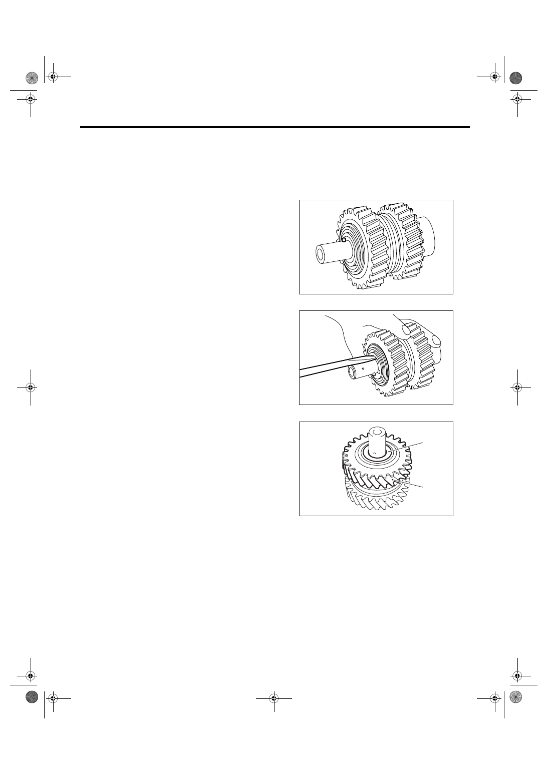
C: DISASSEMBLY
NOTE:
The sleeve and reverse gear engage at a specified
position. Before disassembly, put the mark on en-
gagement position of sleeve and hub.
1) Remove the spring pin.
2) Remove the snap ring.
3) Remove the washer and reverse idler gear.
(A) Washer
(B) Reverse Idler Gear
MT-00617
MT-00618
(B)
(A)
MT-00619
6MT-92
MANUAL TRANSMISSION AND DIFFERENTIAL
Reverse Idler Gear
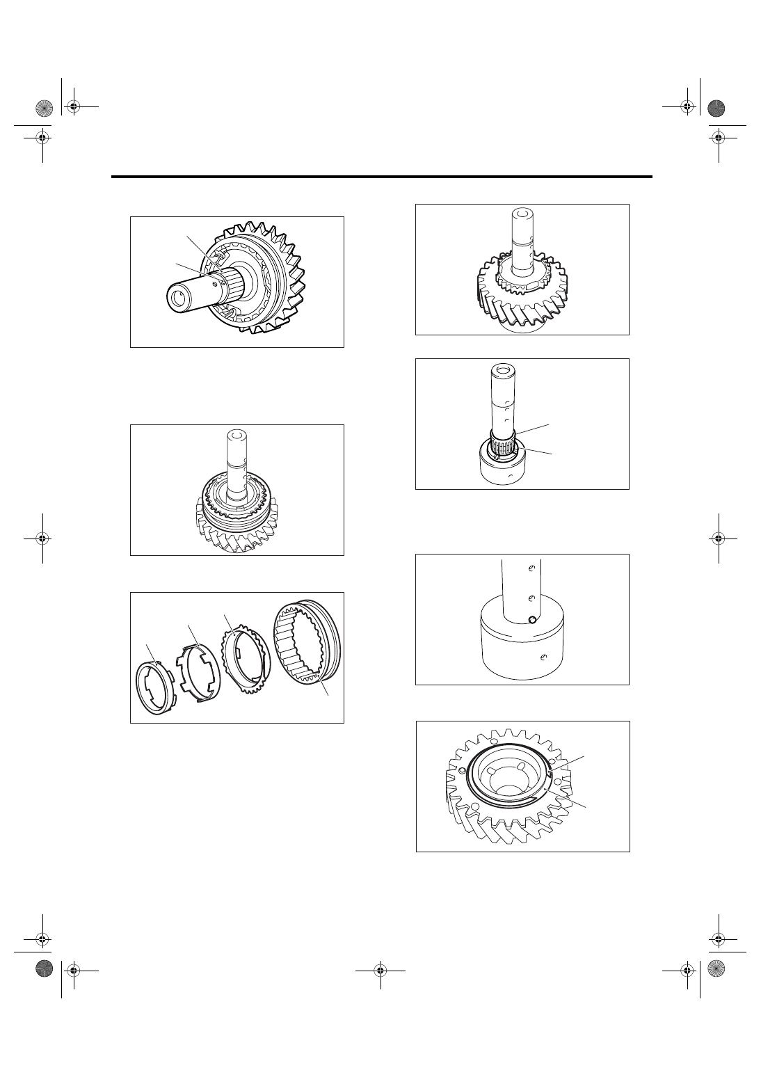
4) Remove the knock pin and reverse idler gear
needle bearing.
5) Remove the collar.
6) Remove the reverse sleeve.
7) Remove the outer baulk ring, reverse synchro
cone and inner baulk ring from reverse sleeve.
8) Remove the reverse idler gear No. 2.
9) Remove the washer and needle bearing.
10) Remove the knock pin.
11) Remove the snap ring and friction plate from
reverse gear.
(A) Knock pin
(B) Reverse idler gear needle bearing
(A) Reverse sleeve
(B) Outer baulk ring
(C) Reverse synchro cone
(D) Inner baulk ring
(A)
(B)
MT-00620
MT-00622
(A)
(B)
(C)
(D)
MT-00623
(A) Needle bearing
(B) Washer
(A) Snap ring
(B) Friction plate
MT-00624
MT-00625
(A)
(B)
MT-00626
MT-00627
(B)
(A)
6MT-93
MANUAL TRANSMISSION AND DIFFERENTIAL
Reverse Idler Gear
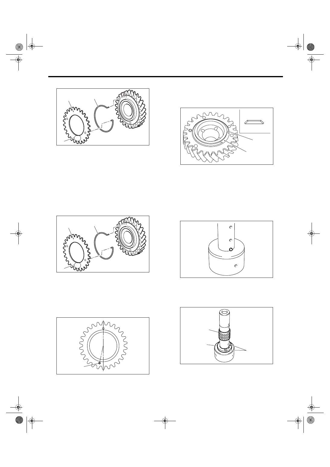
12) Remove the sub gear and spring.
D: ASSEMBLY
1) Install the sub gear and spring.
NOTE:
• Install the spring with white marking on hook part
facing to sub gear side.
• Install the sub gear with stamped mark (mark A)
facing outside.
• Install the spring and sub gear, taking care to in-
stall the sub gear installation hole in proper direc-
tion.
2) Install the friction plate and snap ring.
NOTE:
Be sure the friction plate is installed in proper direc-
tion.
3) Apply sufficient amount of gear oil to the shaft,
needle bearing and inner surface of reverse drive
gear.
4) Install the knock pin.
5) Install the washer and needle bearing.
NOTE:
Install the washer with groove facing to reverse
idler gear.
(A) Sub gear
(B) Spring
(C) Stamped mark (mark A)
(A) Sub gear
(B) Spring
(C) Stamped mark (mark A)
(A) Installation hole
MT-00628
(B)
(A)
(C)
A
MT-00628
(B)
(A)
(C)
A
MT-00629
(A)
A
(A) Friction plate
(B) Snap ring
(C) Snap ring side
(D) Sub gear side
(A) Groove
(B) Washer
(C) Needle bearing
MT-00630
(C)
(D)
(A)
(B)
MT-00626
MT-00631
(C)
(B)
(A)
6MT-94
MANUAL TRANSMISSION AND DIFFERENTIAL
Reverse Idler Gear
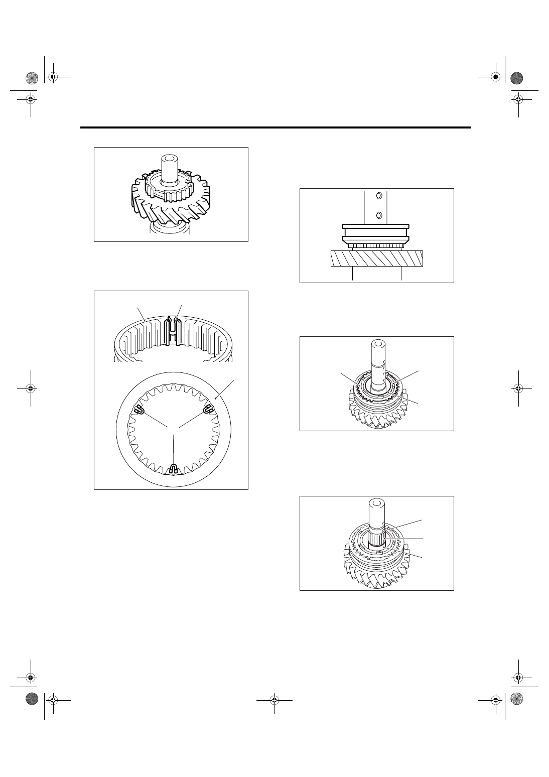
6) Install the reverse idler gear No. 2.
7) Install the shifting insert key in proper place of
reverse sleeve.
NOTE:
Angle of each shifting insert key is 120
°.
8) Install the reverse sleeve to reverse idler gear
No. 2.
NOTE:
Be sure the reverse sleeve is installed in proper di-
rection.
9) Apply sufficient amount of gear oil to the collar,
needle bearing and inner periphery of reverse drive
gear.
10) Install the outer baulk ring, reverse synchro
cone and inner baulk ring.
11) Install the collar and needle bearing, then in-
stall the knock pin.
(A) Reverse sleeve
(B) Shifting insert key
MT-00632
(B)
(A)
(B)
(A)
MT-00633
(A) Outer baulk ring
(B) Reverse synchro cone
(C) Inner baulk ring
(A) Collar
(B) Needle bearing
(C) Knock pin
MT-00634
(A)
(B)
(C)
MT-00635
(C)
(B)
(A)
MT-00636
Нет комментариевНе стесняйтесь поделиться с нами вашим ценным мнением.
Текст