Subaru Legacy (2005 year). Service manual — part 675
6MT-47
MANUAL TRANSMISSION AND DIFFERENTIAL
Extension Case
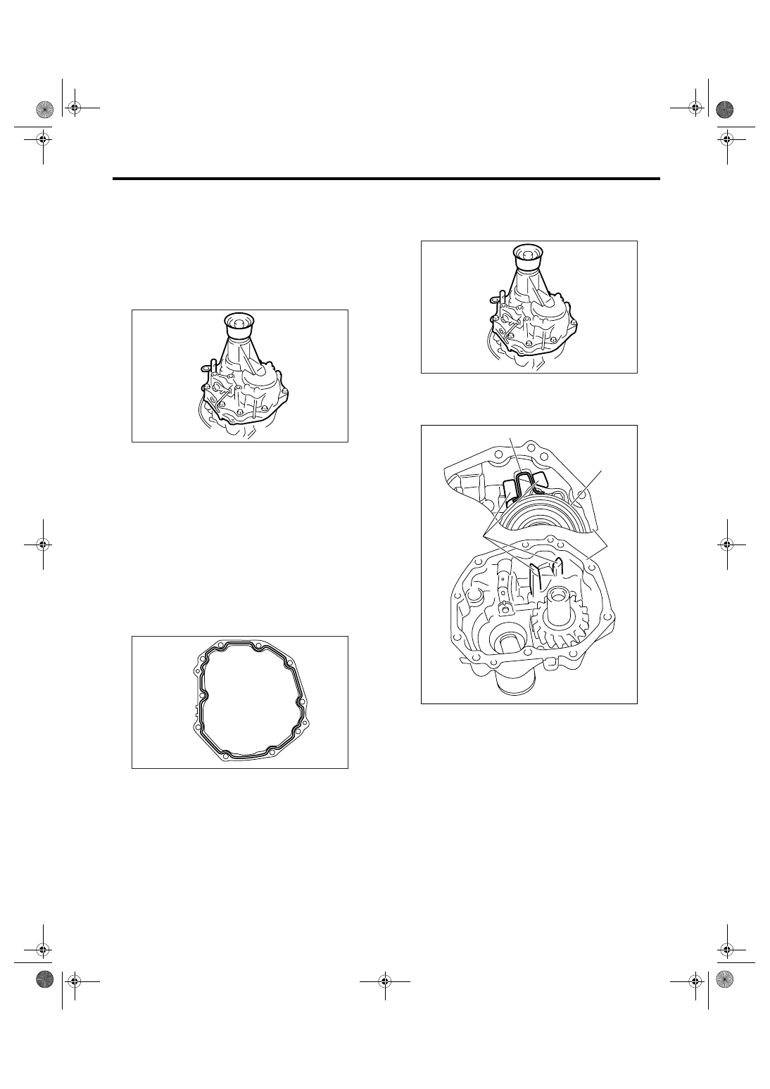
12.Extension Case
A: REMOVAL
1) Remove the manual transmission assembly
from vehicle. <Ref. to 6MT-34, REMOVAL, Manual
Transmission Assembly.>
2) Prepare the transmission for overhaul. <Ref. to
6MT-40, Preparation for Overhaul.>
3) Remove the extension case.
4) Completely remove the remaining liquid gasket
from the extension case and transmission case.
B: INSTALLATION
1) Select the transfer driven gear thrust washer,
and then install to extension case. <Ref. to 6MT-49,
ADJUSTMENT, Extension Case.>
2) Apply oil lightly to the outer periphery of bearing
cone, and then install to extension case.
3) Select the thrust washer of transfer drive gear,
and then install to center differential.
4) Apply liquid gasket to the transmission case.
Liquid gasket:
THREE BOND 1215 (Part No. 004403007)
5) Install the extension case.
Tightening torque:
48 N
⋅
m (4.9 kgf-m, 35.4 ft-lb)
NOTE:
Insert the stopper portion of center differential be-
tween extension guides.
6) Install the manual transmission assembly into
vehicle. <Ref. to 6MT-36, INSTALLATION, Manual
Transmission Assembly.>
MT-00475
MT-00476
(A) Extension guide
(B) Stopper
(C) Center Differential
(D) Extension case
MT-00475
MT-00973
(A)
(B)
(C)
(D)
6MT-48
MANUAL TRANSMISSION AND DIFFERENTIAL
Extension Case
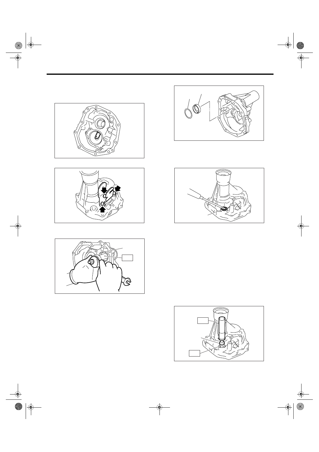
C: DISASSEMBLY
1) Remove the transfer drive gear. <Ref. to 6MT-
56, REMOVAL, Transfer Drive Gear.>
2) Remove the extension guide.
3) Remove the shift bracket.
4) Using the ST, remove the bearing cone.
ST
18758AA000
PULLER
5) Remove the thrust washer and oil plate.
6) Remove the shifter arm oil seal.
7) Remove the reverse check system. <Ref. to
6MT-53, REMOVAL, Reverse Check System.>
8) Remove the extension case oil seal. <Ref. to
6MT-30, REPLACEMENT, Oil Seal.>
D: ASSEMBLY
1) Install the reverse check system. <Ref. to 6MT-
54, INSTALLATION, Reverse Check System.>
2) Install the extension case oil seal. <Ref. to 6MT-
30, REPLACEMENT, Oil Seal.>
3) Using the ST, install the shifter arm oil seal.
ST1
18657AA000 INSTALLER
ST2
18671AA000 OIL SEAL GUIDE
(A) Bearing cone
MT-00477
MT-00478
MT-00479
(A)
ST
(A) Thrust washer
(B) Oil plate
(A) Oil seal
(A) Oil seal
(A)
(B)
MT-00480
MT-00481
(A)
MT-00482
(A)
ST1
ST2
6MT-49
MANUAL TRANSMISSION AND DIFFERENTIAL
Extension Case
4) Install the oil plate.
5) Select the bearing thrust washer, and then install
to extension case. <Ref. to 6MT-49, ADJUST-
MENT, Extension Case.>
6) Apply oil lightly to the outer periphery of bearing
cone, and then install to extension case.
7) Install the shift bracket.
Tightening torque:
25 N
⋅
m (2.5 kgf-m, 18.4 ft-lb)
8) Install the extension guide, and then install the
transfer driven gear. <Ref. to 6MT-56, INSTALLA-
TION, Transfer Drive Gear.>
E: INSPECTION
1) Check there is no damage or crack on extension
case. If there is damage or crack, replace the ex-
tension case.
2) Check the oil seal and the mating surface of ex-
tension case and transmission case for oil leakage.
If there is oil leakage, replace the oil seal and liquid
gasket.
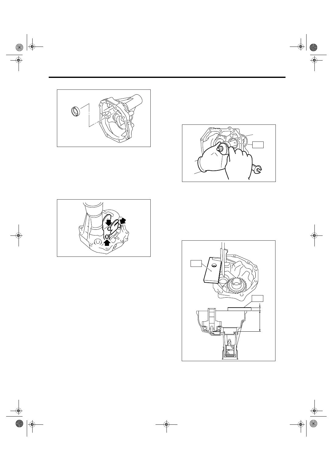
F: ADJUSTMENT
1. TRANSFER DRIVEN GEAR BEARING
THRUST WASHER ADJUSTMENT
1) Using the ST, remove the bearing cone from ex-
tension case.
ST
18758AA000
PULLER
2) Remove the thrust washer.
3) Measure the depth “Z” between end of extension
case and contact point of bearing cone.
ST
499575500
GAUGE
NOTE:
To measure the depth “Z”, subtract the thickness of
ST [15 mm (0.59 in)] from the measured value.
4) Remove the transfer driven gear. <Ref. to 6MT-
58, REMOVAL, Transfer Driven Gear.>
5) Remove the center differential. <Ref. to 6MT-60,
REMOVAL, Center Differential.>
MT-00483
MT-00478
(A) Bearing cone
(A) 15 mm (0.59 in)
MT-00479
(A)
ST
MT-00484
(A)
Z
ST
ST
6MT-50
MANUAL TRANSMISSION AND DIFFERENTIAL
Extension Case
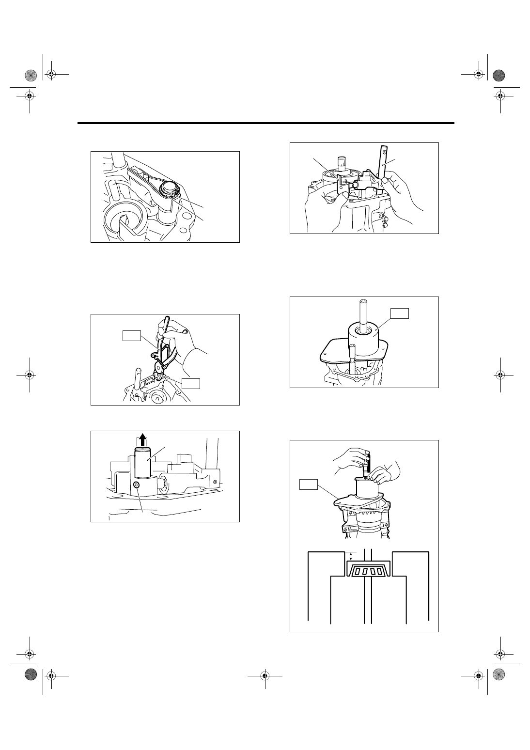
6) Remove the snap ring and flat washer from se-
lector arm part.
7) Using the ST, remove the neutral set spring and
the support.
ST1
18756AA000 CLAW
ST2
399893600
PLIERS
8) Raise the striking rod up, then remove the spring
pin.
9) Remove the selector arm No. 2 and shifter arm.
10) Install the bearing cone to transfer driven gear.
11) Set the ST.
ST
18831AA000
GAUGE
12) Rotate the transfer driven gear approx. ten
times to get the bearing accustomed.
13) Measure the depth “Y” between end of ST and
bearing cone.
ST
18831AA000
GAUGE
(A) Snap ring
(B) Flat washer
(A) Striking rod
(B) Spring pin
MT-01306
(B)
(A)
MT-01092
ST2
ST2
ST1
(A)
(B)
MT-01307
(A) Selector arm No. 2
(B) Shifter arm
(B)
(A)
MT-01308
MT-00489
ST
MT-00490
Y
ST
Нет комментариевНе стесняйтесь поделиться с нами вашим ценным мнением.
Текст