Subaru Legacy (2005 year). Service manual — part 676
6MT-51
MANUAL TRANSMISSION AND DIFFERENTIAL
Extension Case
14) Calculate the value “t” of transfer driven gear
bearing thrust washer using the following equation.
t = Z
− (100 − Y) − {−0.04 to 0.11 mm (−0.0016 to
0.0043 in)}
15) Select the nearest thrust washer from the fol-
lowing table, according to the calculated value “t”.
Standard clearance between thrust washer and
taper roller bearing:
−
0.04 — 0.11 mm (
−
0.0016 — 0.0043 in)
NOTE:
Be sure that it is within standard clearance range.
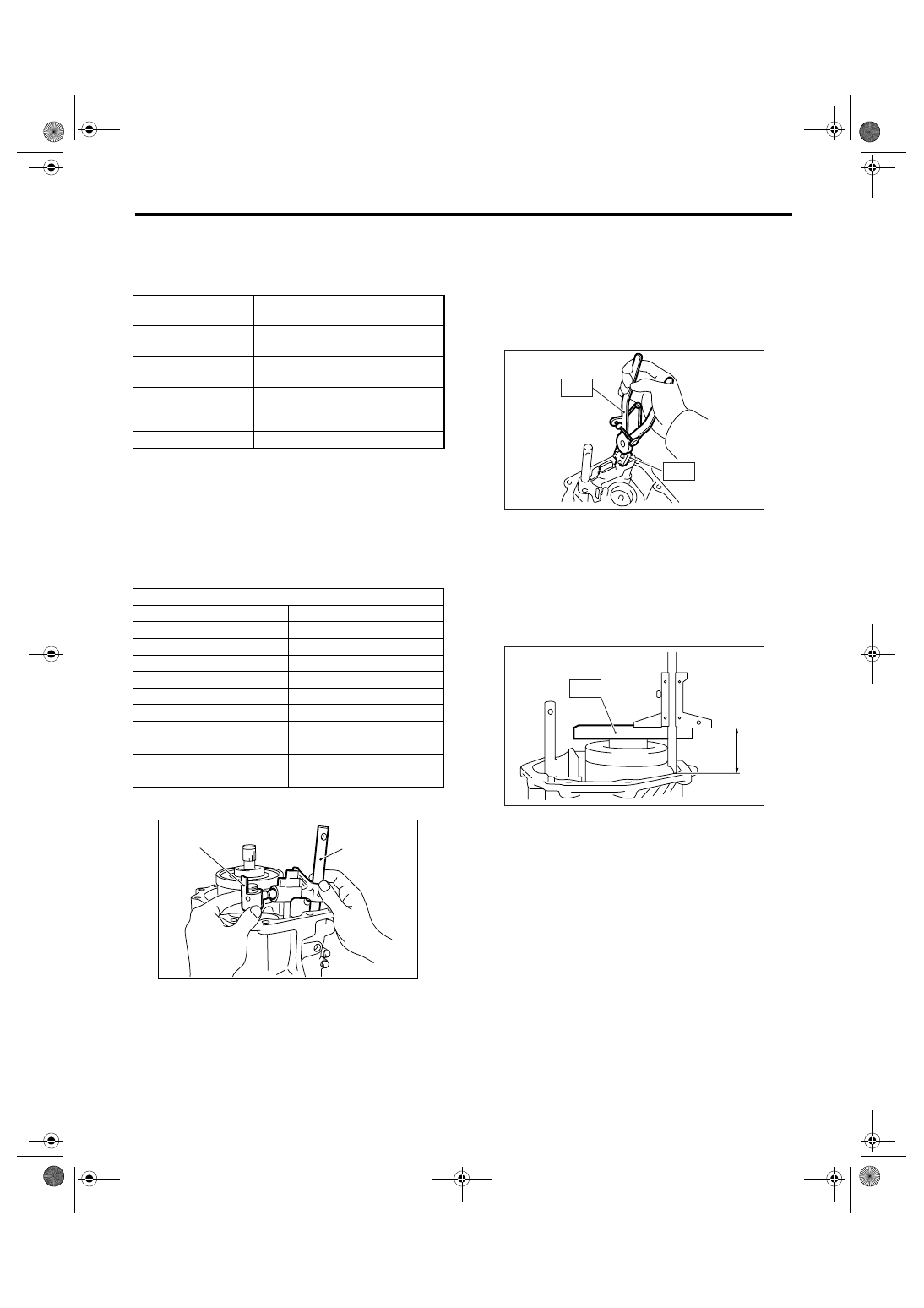
16) Remove the selector arm No. 2 and shifter arm.
17) Install the spring pin.
NOTE:
Use new spring pin.
18) Using the ST, install the neutral set spring and
support.
ST1
18756AA000 CLAW
ST2
399893600
PLIERS
19) Install the flat washer and snap ring.
20) Install the center differential.
2. SELECTING THE TRANSFER DRIVE
GEAR THRUST WASHER
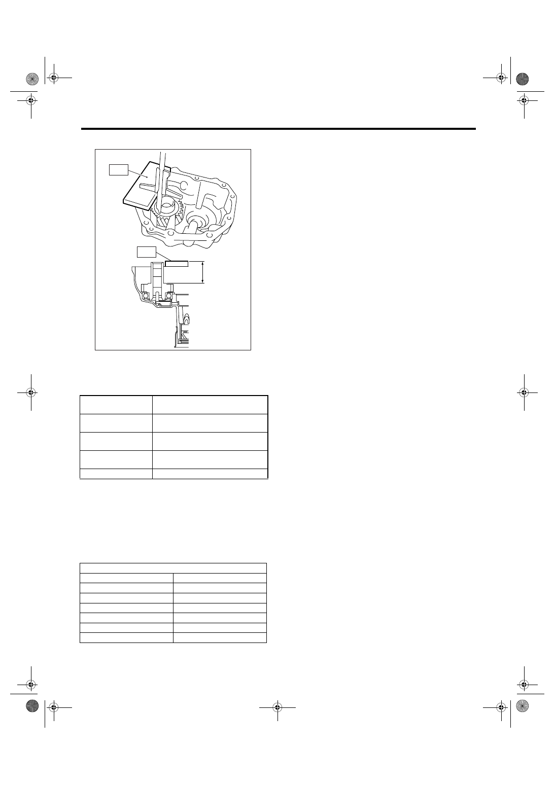
1) Measure the height “Z” between end of transmis-
sion case and end of ST.
ST
499575500
GAUGE
2) Measure the depth “Y” between end of ST and
transfer drive gear.
t
mm (in)
Thickness of transfer driven gear
bearing thrust washer
Y
mm (in)
Depth from end of ST to bearing
cone
Z
mm (in)
Depth from end of extension case
to contact point of bearing cone
−0.04 — 0.11 mm
(
−0.0016 — 0.0043
in)
Standard clearance between thrust
washer and taper roller bearing
100 mm (3.94 in)
Height of ST
Thrust washer (50
× 61 × t)
Part No.
Thickness t mm (in)
803050060
0.50 (0.0197)
803050062
0.60 (0.0236)
803050064
0.70 (0.0276)
803050066
0.80 (0.0315)
803050068
0.90 (0.0354)
803050070
1.00 (0.0394)
803050072
1.10 (0.0433)
803050074
1.20 (0.0472)
803050076
1.30 (0.0512)
803050078
1.40 (0.0551)
(A) Selector arm No. 2
(B) Shifter arm
(B)
(A)
MT-01308
MT-01092
ST2
ST2
ST1
MT-00492
Z
ST
6MT-52
MANUAL TRANSMISSION AND DIFFERENTIAL
Extension Case
ST
499575500
GAUGE
3) Calculate the value “t” of transfer drive gear
thrust washer using the following equation.
t = {Y
− 15 mm (0.59 in)} − {Z − 15 mm (0.59 in)} −
0.45 — 0.65 mm (0.018
—
0.026 in)
4) Select the nearest thrust washer from the follow-
ing table, according to the calculated value “t”.
Standard clearance between thrust washer and
transfer drive gear.
0.45 — 0.65 mm (0.018 — 0.026 in)
NOTE:
Be sure that it is within standard clearance range.
5) Install the selected thrust washer.
t
mm (in)
Thickness of transfer drive gear
thrust washer
Y
mm (in)
Depth from end of ST to transfer
drive gear
Z
mm (in)
Height from end of transmission
case to the end of ST
0.45 to 0.65 mm
(0.018 to 0.026 in)
Standard clearance between thrust
washer and transfer drive gear.
15 mm (0.59 in)
Thickness of ST
Thrust washer (36.3
× 52 × t)
Part No.
Thickness mm (in)
803036070
0.80 (0.0315)
803036071
0.95 (0.0374)
803036072
1.10 (0.0433)
803036073
1.25 (0.0492)
803036074
1.40 (0.0551)
803036075
0.65 (0.0256)
MT-00493
Y
ST
ST
6MT-53
MANUAL TRANSMISSION AND DIFFERENTIAL
Reverse Check System
13.Reverse Check System
A: REMOVAL
1) Remove the manual transmission assembly
from vehicle. <Ref. to 6MT-34, REMOVAL, Manual
Transmission Assembly.>
2) Prepare the transmission for overhaul. <Ref. to
6MT-40, Preparation for Overhaul.>
3) Remove the extension case. <Ref. to 6MT-47,
REMOVAL, Extension Case.>
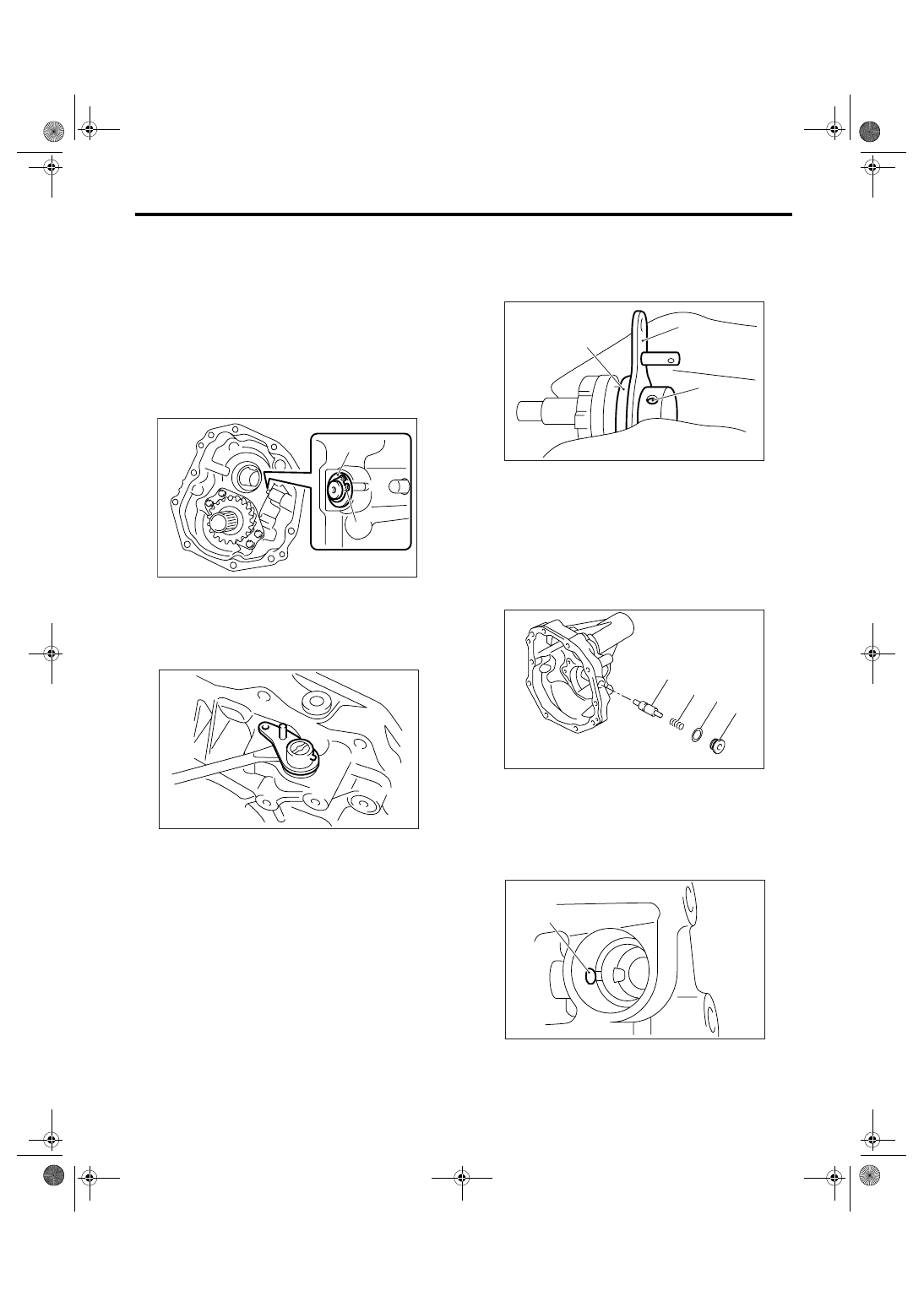
4) Remove the snap ring and washer from reverse
check shaft.
5) Remove the reverse check shaft and spring from
the extension case.
6) Remove the spring pin, then remove the reverse
check lever and oil seal from reverse check shaft.
NOTE:
Use a new oil seal.
7) Remove the plug from extension case, then re-
move the gasket, spring and plunger.
NOTE:
Use a new gasket.
8) Remove the reverse lock plunger.
(A) Snap ring
(B) Washer
(A)
(B)
MT-00494
MT-00495
(A) Spring pin
(B) Reverse check lever
(C) Oil seal
(A) Plug
(B) Gasket
(C) Spring
(D) Plunger
(A) Reverse lock plunger
(A)
(C)
(B)
MT-00496
(A)
(B)
(C)
(D)
MT-00497
(A)
MT-00498
6MT-54
MANUAL TRANSMISSION AND DIFFERENTIAL
Reverse Check System
B: INSTALLATION
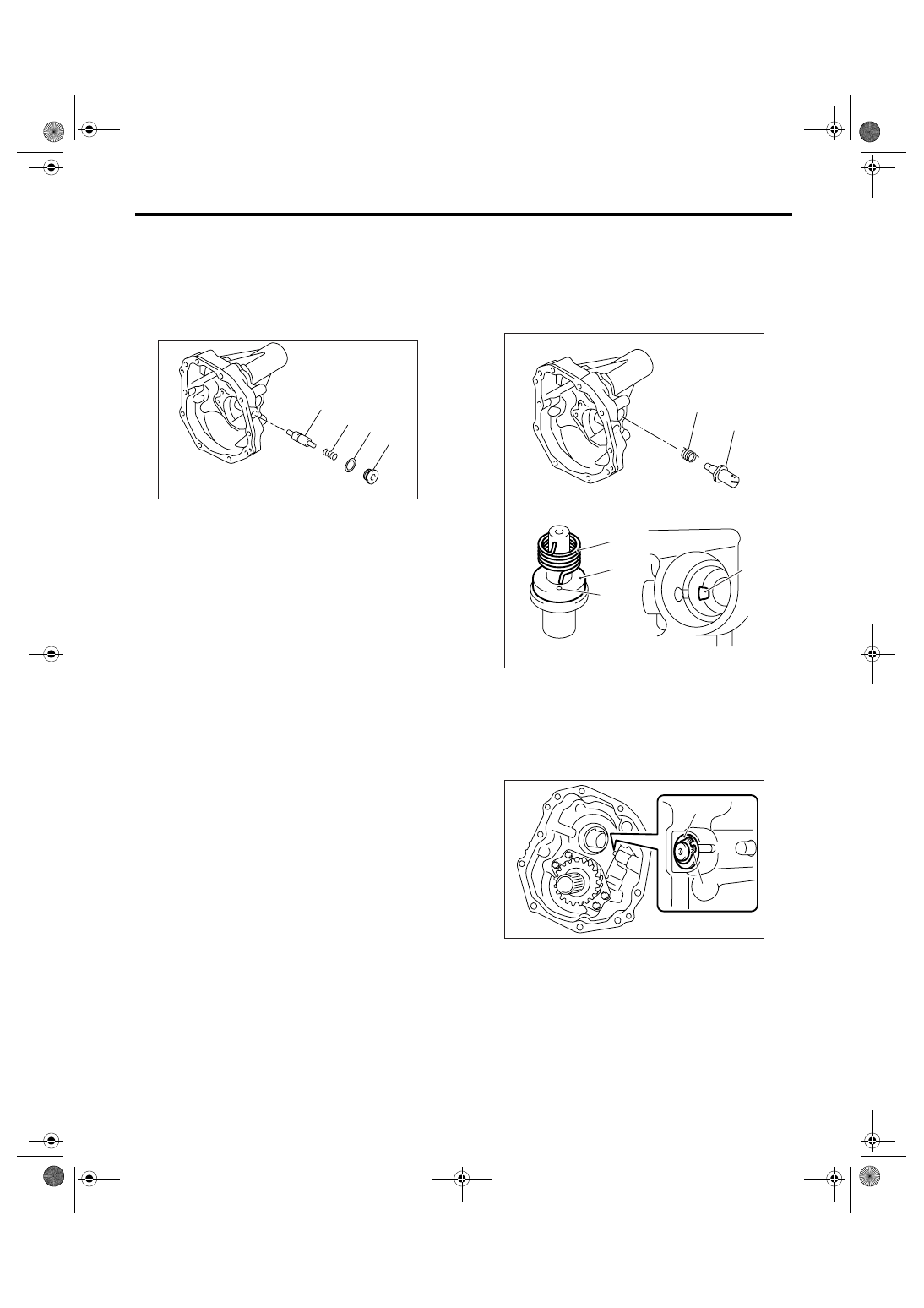
1) Insert the reverse lock plunger.
2) Install in the order of reverse checking plug,
spring, gasket and plug.
Tightening torque:
41 N
⋅
m (4.2 kgf-m, 30.2 ft-lb)
3) Install the spring and reverse check shaft to ex-
tension case.
NOTE:
Be sure the spring end aligns with the hole of re-
verse check shaft and the cutout portion of exten-
sion case.
4) Install the washer and snap ring.
(A) Plug
(B) Gasket
(C) Spring
(D) Reverse checking plug
(A)
(B)
(C)
(D)
MT-00497
(A) Reverse check shaft
(B) Spring
(C) Hole
(D) Cutout portion
(A) Snap ring
(B) Washer
(A)
(A)
(C)
(D)
(B)
(B)
MT-00499
(A)
(B)
MT-00494
Нет комментариевНе стесняйтесь поделиться с нами вашим ценным мнением.
Текст