Subaru Legacy (2005 year). Service manual — part 677
6MT-55
MANUAL TRANSMISSION AND DIFFERENTIAL
Reverse Check System
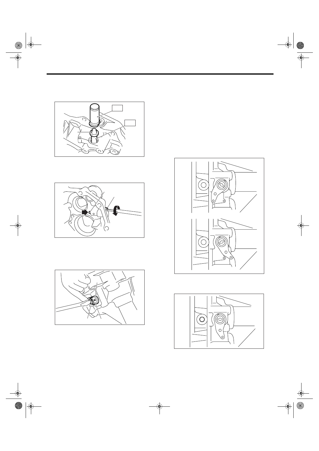
5) Set the ST1 to reverse check shaft. Install a new
oil seal, then press with ST2.
ST1
18671AA000 OIL SEAL GUIDE
ST2
18657AA010 INSTALLER
6) Insert the reverse check lever, then rotate the re-
verse check shaft until the plunger can be pushed.
7) Align the hole of reverse check lever and reverse
check shaft, then install the spring pin.
8) Make sure the reverse check operates correctly.
<Ref. to 6MT-55, INSPECTION, Reverse Check
System.>
9) Install the extension case. <Ref. to 6MT-47, IN-
STALLATION, Extension Case.>
10) Install the manual transmission assembly into
vehicle. <Ref. to 6MT-36, INSTALLATION, Manual
Transmission Assembly.>
C: INSPECTION
1) Check there is no damage on each part.
2) Check that the reverse check lever operates
smoothly.
3) Check that there is no oil leakage on oil seal part
of reverse check shaft. If there is oil leakage, re-
place the oil seal.
4) Inspect the reverse check operation.
(1) The plunger can be pushed or the gear can
be shifted to reverse, when reverse check lever
is in the following position.
(2) The plunger cannot be pushed or the gear
cannot be shifted to reverse, when reverse
check lever is in the following position.
5) If not as specified, reassemble the reverse
check system.
(A) Oil seal
(A) Plunger
(B) Reverse check shaft
(A) Reverse check shaft
(B) Reverse check lever
(C) Hole
MT-00500
(A)
ST2
ST1
(A)
(B)
MT-00501
(A)
(B)
(C)
MT-00502
MT-00503
MT-00504
6MT-56
MANUAL TRANSMISSION AND DIFFERENTIAL
Transfer Drive Gear
14.Transfer Drive Gear
A: REMOVAL
1) Remove the manual transmission assembly
from vehicle. <Ref. to 6MT-34, REMOVAL, Manual
Transmission Assembly.>
2) Prepare the transmission for overhaul. <Ref. to
6MT-40, Preparation for Overhaul.>
3) Remove the extension case. <Ref. to 6MT-47,
REMOVAL, Extension Case.>
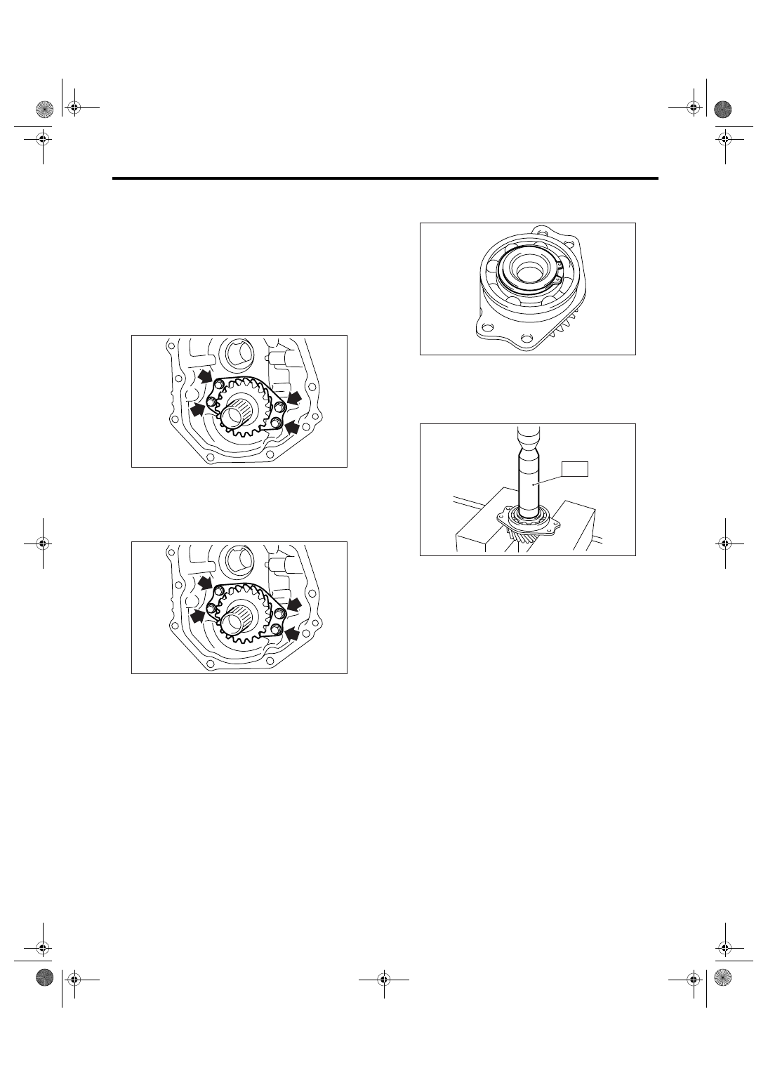
4) Remove the transfer drive gear.
B: INSTALLATION
1) Install the transfer drive gear.
Tightening torque:
25 N
⋅
m (2.5 kgf-m, 18.4 ft-lb)
2) If the ball bearing, transfer drive gear or snap
ring is replaced, select the transfer drive gear thrust
washer. <Ref. to 6MT-48, ASSEMBLY, Extension
Case.>
3) Install the extension case. <Ref. to 6MT-47, IN-
STALLATION, Extension Case.>
4) Install the manual transmission assembly into
vehicle. <Ref. to 6MT-36, INSTALLATION, Manual
Transmission Assembly.>
C: DISASSEMBLY
1) Remove the snap ring.
2) Using the ST, remove the bearing.
ST
499877000
RACE 4-5 INSTALLER
NOTE:
Use a new ball bearing.
MT-00505
MT-00505
MT-00506
MT-00507
ST

6MT-57
MANUAL TRANSMISSION AND DIFFERENTIAL
Transfer Drive Gear
D: ASSEMBLY
1) Using the ST, install the ball bearing.
ST1
499247400
INSTALLER
ST2
398497701
SEAT
2) Install the snap ring.
3) Inspect the clearance between snap ring and
ball bearing. <Ref. to 6MT-57, INSPECTION,
Transfer Drive Gear.>
E: INSPECTION
1) Bearing
Replace the bearings in the following cases.
• When there are breakage and rust on the bear-
ings.
• When there are wear or damage.
• When bearings that fail to turn smoothly or make
noise.
2) Drive gear
Replace the drive gear in the following case:
• When their tooth surface and shaft are exces-
sively broken or damaged.
3) Measure the clearance between snap ring and
inner race of ball bearing with a thickness gauge.
Standard clearance between snap ring and in-
ner race:
0 — 0.15 mm (0 — 0.0059 in)
4) If the measurement is not within the range, se-
lect a suitable snap ring from the table below.
NOTE:
Be sure that it is within standard clearance range.
After replacement of the snap ring, inspect the
clearance again.
MT-00508
ST2
ST1
MT-00506
Snap ring
Part No.
Thickness mm (in)
805045050
1.76 (0.069)
805045060
1.88 (0.074)
805045070
2.00 (0.079)
MT-00509
6MT-58
MANUAL TRANSMISSION AND DIFFERENTIAL
Transfer Driven Gear
15.Transfer Driven Gear
A: REMOVAL
1) Remove the manual transmission assembly
from vehicle. <Ref. to 6MT-34, REMOVAL, Manual
Transmission Assembly.>
2) Prepare the transmission for overhaul. <Ref. to
6MT-40, Preparation for Overhaul.>
3) Remove the extension case. <Ref. to 6MT-47,
REMOVAL, Extension Case.>
4) Remove the transfer driven gear.
B: INSTALLATION
1) Install the transfer driven gear.
2) If the bearing or transfer driven gear is replaced,
select the transfer driven thrust washer. <Ref. to
6MT-49, ADJUSTMENT, Extension Case.>
3) Install the extension case. <Ref. to 6MT-47, IN-
STALLATION, Extension Case.>
4) Install the manual transmission assembly into
vehicle. <Ref. to 6MT-36, INSTALLATION, Manual
Transmission Assembly.>
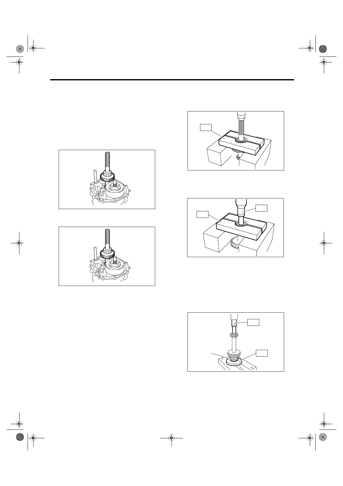
C: DISASSEMBLY
1) Using the ST, remove the roller bearing (exten-
sion case side).
ST
498515700
REMOVER
2) Using the ST1 and ST2, remove the roller bear-
ing (transmission case side).
ST1
899858600
REMOVER
ST2
899864100
REMOVER
D: ASSEMBLY
1) Using the ST, install the roller bearing (extension
case side).
ST1
398177700
INSTALLER
ST2
899864100
REMOVER
NOTE:
Do not apply pressure in excess of 10 kN (1 ton, 1.1
US ton, 1.0 Imp ton).
2) Using the ST, install the roller bearing of trans-
mission case side.
ST
499757002
INSTALLER
MT-00510
MT-00510
(A) Roller bearing
MT-00511
ST
MT-00512
ST2
ST1
MT-00513
(A)
ST1
ST2
Нет комментариевНе стесняйтесь поделиться с нами вашим ценным мнением.
Текст