Subaru Legacy (2005 year). Service manual — part 571
4AT(diag)-121
AUTOMATIC TRANSMISSION (DIAGNOSTICS)
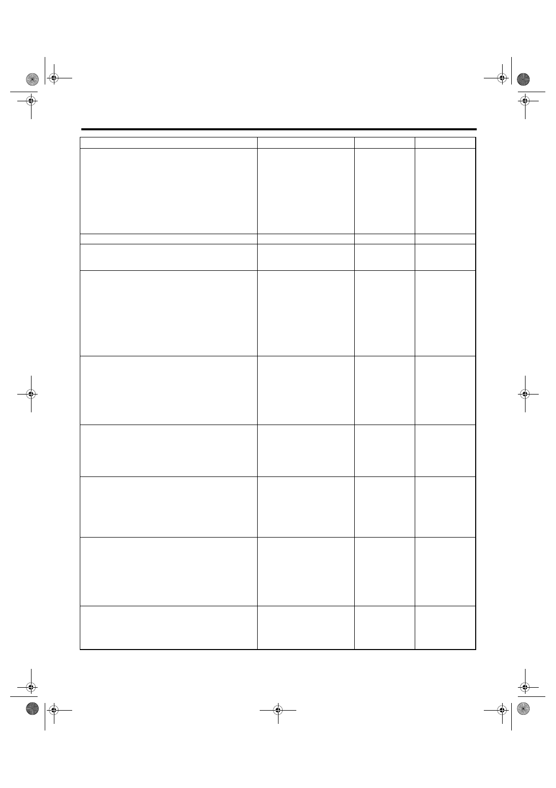
Diagnostic Procedure without Diagnostic Trouble Code (DTC)
Step
Check
Yes
No
1
CONFIRM EQUIPMENT OF VEHICLE.
Is the vehicle equipped with
VDC?
Go to “CHECK
MANUAL MODE
SWITCH”. <Ref. to
4AT(diag)-123,
CHECK MANUAL
MODE SWITCH,
Diagnostic Proce-
dure without Diag-
nostic Trouble
Code (DTC).>
2
CHECK SPARE FUSE.
Is the spare fuse OK?
Replace the fuse.
3
CHECK FWD SWITCH.
Connect the Subaru Select Monitor to data link
connector.
When the fuse is inserted to
FWD switch, does the LED
light up?
4
CHECK COMBINATION METER.
Does the AWD warning light
illuminate?
Go to “CHECK
MANUAL MODE
SWITCH”. <Ref. to
4AT(diag)-123,
CHECK MANUAL
MODE SWITCH,
Diagnostic Proce-
dure without Diag-
nostic Trouble
Code (DTC).>
5
CHECK HARNESS CONNECTOR BETWEEN
TCM AND FWD SWITCH.
1) Turn the ignition switch to OFF.
2) Disconnect the connector from TCM.
3) Measure the resistance of harness
between TCM and FWD switch connector.
Connector & terminal
(B55) No. 17 — (F27) No. 18:
Is the resistance less than 1
Ω?
Repair the open
circuit of harness
between TCM and
FWD switch con-
nector.
6
CHECK HARNESS CONNECTOR BETWEEN
FWD SWITCH AND CHASSIS GROUND.
Measure the resistance of harness between
FWD switch and chassis ground.
Connector & terminal
(F27) No. 19 — Chassis ground:
Is the resistance less than 1
Ω?
Repair the open
circuit of harness
between FWD
switch connector
and chassis
ground.
7
CHECK HARNESS CONNECTOR BETWEEN
TCM AND FWD SWITCH.
Measure the resistance of harness connector
between TCM and body to make sure that cir-
cuit does not short.
Connector & terminal
(B55) No. 17 — Chassis ground:
Is the resistance more than 1
M
Ω?
Repair the short
circuit of harness
between TCM and
FWD switch con-
nector.
8
CHECK INPUT SIGNAL FOR TCM.
1) Turn the ignition switch to OFF.
2) Connect the connector to TCM.
3) Turn the ignition switch to ON.
4) Measure the signal voltage for TCM while
installing the fuse to FWD switch connector.
Connector & terminal
(B55) No. 17 (+) — Chassis ground (
−
):
Is the voltage less than 1 V?
9
CHECK INPUT SIGNAL FOR TCM.
Measure the signal voltage for TCM while
removing the fuse from FWD switch connector.
Connector & terminal
(B55) No. 17 (+) — Chassis ground (
−
):
Is the voltage more than 10.5
V?
Replace the TCM.
<Ref. to 4AT-66,
Transmission Con-
trol Module
(TCM).>
4AT(diag)-122
AUTOMATIC TRANSMISSION (DIAGNOSTICS)
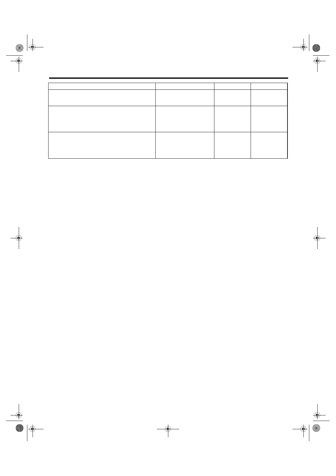
Diagnostic Procedure without Diagnostic Trouble Code (DTC)
10
CHECK BODY INTEGRATED MODULE.
Check DTC of body integrated module.
Is DTC of CAN communication
displayed?
Perform the diag-
nosis according to
DTC.
11
CHECK COMBINATION METER.
Check AWD warning light. <Ref. to IDI-3,
INSPECTION, Combination Meter System.>
Is the AWD warning light OK?
Replace the com-
bination meter
assembly. <Ref. to
IDI-15, Combina-
tion Meter.>
12
CHECK POOR CONTACT.
Is there poor contact in FWD
switch circuit?
Repair the poor
contact.
Replace the TCM.
<Ref. to 4AT-66,
Transmission Con-
trol Module
(TCM).>
Step
Check
Yes
No
4AT(diag)-123
AUTOMATIC TRANSMISSION (DIAGNOSTICS)
Diagnostic Procedure without Diagnostic Trouble Code (DTC)
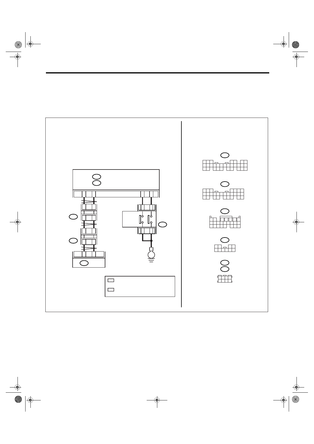
B: CHECK MANUAL MODE SWITCH
DIAGNOSIS:
Input signal circuit of manual mode switch is open or shorted.
TROUBLE SYMPTOM:
Does not shift on manual mode.
WIRING DIAGRAM:
• LHD model
AT-03166
B281
C:
B280
B:
B20
B30
C25
C15
3
12
B116
TCM
B54
B280
B54
B281
8
7
6
5
4
3
2
1
22
23
21
20
19
16
15
14
13
12
11
10
9
17
30
18
29
28
27
26
25
24
8
7
6
5
4
3
2
1
22 23
21
20
19
16
15
14
13
12
11
10
9
17 18
28
27
26
25
24
8
3
4
5
6
7
2
1
18 19 20
17
16
15
14
13
12
11
10
9
24
23
22
21
B116
10
9
8
7
6
5
4
3
2
1
E
BODY INTEGRATED MODULE
SELECT
LEVER
B:
C:
2
4
5
7
B352
JOINT
CONNECTOR
B355
JOINT
CONNECTOR
B352
B355
1 2 3 4
5 6 7 8
2
*
2
*
1
*
1
*
1
*
: TERMINAL No. RANDOM ARRANGEMENT
AMONG 1,2,5, AND 6
2
*
: TERMINAL No. RANDOM ARRANGEMENT
AMONG 3,4,7, AND 8
5
9
6
10
MANUAL
MODE
SWITCH
UP
DOWN
4AT(diag)-124
AUTOMATIC TRANSMISSION (DIAGNOSTICS)
Diagnostic Procedure without Diagnostic Trouble Code (DTC)
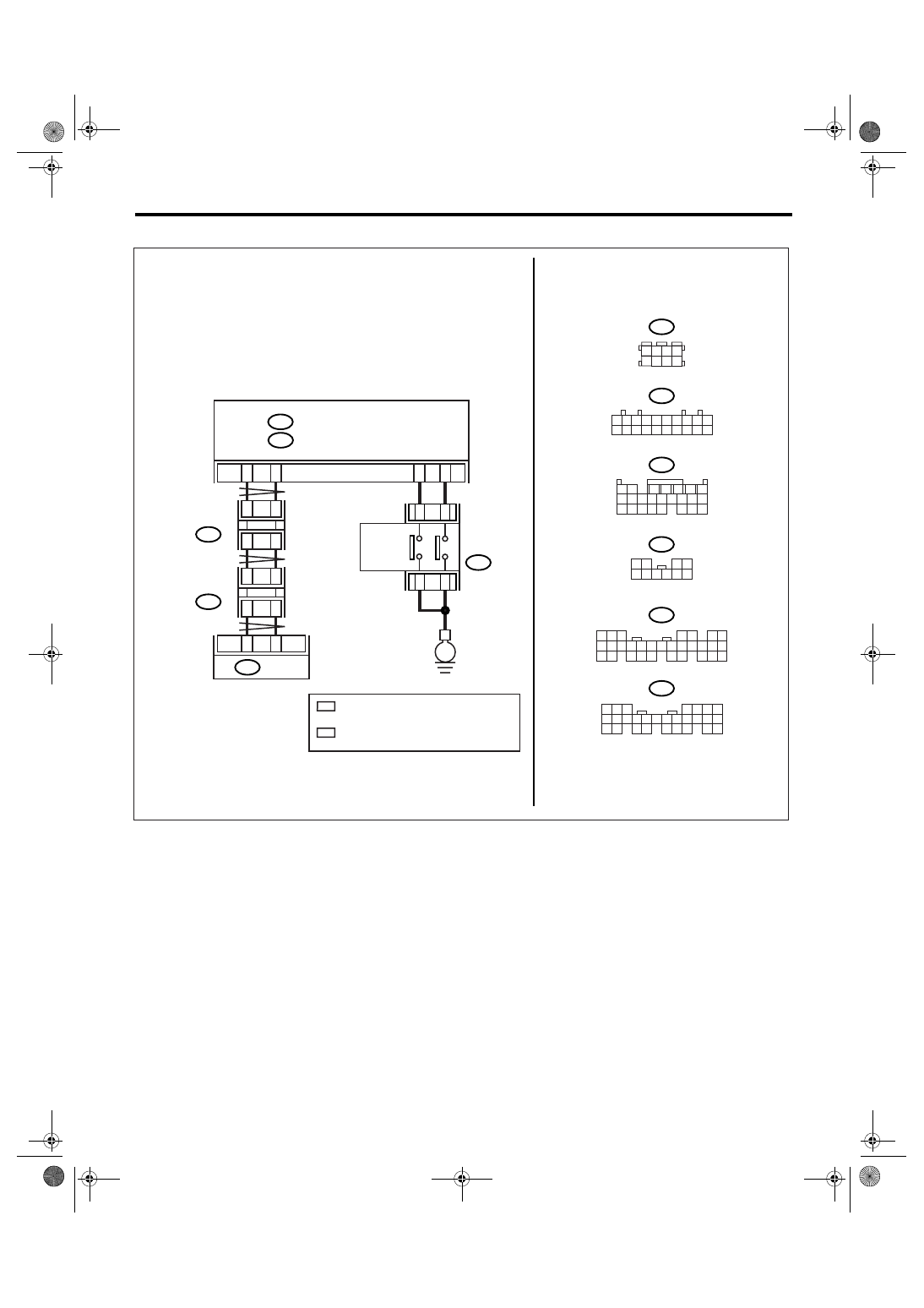
• RHD model
AT-03167
B281
C:
B280
B:
B20
B30
C25
3
12
8
B352
B116
2
4
B53
TCM
B54
C15
E
BODY INTEGRATED MODULE
JOINT
CONNECTOR
JOINT
CONNECTOR
SELECT
LEVER
B280
B352
B53
B54
B281
10
9
8
7
6
5
4
3
2
1
20
19
18
17
16
15
14
13
12
11
8
7
6
5
4
3
2
1
22
23
21
20
19
16
15
14
13
12
11
10
9
17
30
18
29
28
27
26
25
24
8
7
6
5
4
3
2
1
22 23
21
20
19
16
15
14
13
12
11
10
9
17 18
28
27
26
25
24
8
3
4
5
6
7
2
1
18 19 20
17
16
15
14
13
12
11
10
9
24
23
22
21
B116
10
9
8
7
6
5
4
3
2
1
B:
C:
2
1
3 4
8
7
6
5
2
*
2
*
1
*
1
*
6
1
*
: TERMINAL No. RANDOM ARRANGEMENT
AMONG 8,18, AND 19
2
*
: TERMINAL No. RANDOM ARRANGEMENT
AMONG 9,10, AND 20
5
9
6
10
MANUAL
MODE
SWITCH
UP
DOWN
Нет комментариевНе стесняйтесь поделиться с нами вашим ценным мнением.
Текст