Subaru Legacy (2005 year). Service manual — part 572
4AT(diag)-125
AUTOMATIC TRANSMISSION (DIAGNOSTICS)
Diagnostic Procedure without Diagnostic Trouble Code (DTC)
Step
Check
Yes
No
1
CHECK SPORT SHIFT SWITCH.
1) Shift the select lever to manual mode.
2) Shift and hold the select lever to up side.
3) Read the Up Switch data of TCM using
Subaru Select Monitor. <Ref. to 4AT(diag)-16,
READ CURRENT DATA, OPERATION, Subaru
Select Monitor.>
Is ON displayed?
2
CHECK MANUAL MODE SWITCH.
1) Shift and hold the select lever to down side.
2) Read the Down Switch data of TCM using
Subaru Select Monitor. <Ref. to 4AT(diag)-16,
READ CURRENT DATA, OPERATION, Subaru
Select Monitor.>
Is ON displayed?
Go to “CHECK
SPORT INDICA-
TOR” procedures.
<Ref. to 4AT(diag)-
128, CHECK
SPORT INDICA-
TOR., Diagnostic
Procedure without
Diagnostic Trou-
ble Code (DTC).>
3
CHECK BODY INTEGRATED MODULE.
1) Turn the ignition switch to ON.
2) Shift and hold the select lever to up side.
3) Read the TIP UP SW data of body inte-
grated module using Subaru Select Monitor.
<Ref. to LAN(diag)-14, OPERATION, Subaru
Select Monitor.>
Is ON displayed?
4
CHECK BODY INTEGRATED MODULE.
Check DTC of body integrated module. <Ref.
to LAN(diag)-14, OPERATION, Subaru Select
Monitor.>
Is DTC of CAN communication
displayed?
Perform the diag-
nosis according to
DTC.
Check the TCM.
5
CHECK MANUAL MODE SWITCH GROUND
CIRCUIT.
1) Turn the ignition switch to OFF.
2) Disconnect the connector from manual
mode switch.
3) Measure the resistance of harness
between manual mode switch connector and
chassis ground.
Connector & terminal
(B116) No. 6 — Chassis ground:
Is the resistance less than 1
Ω?
Repair the open
circuit of harness
between manual
mode switch and
chassis ground.
6
CHECK MANUAL MODE SWITCH.
Measure the resistance between manual mode
switch terminals.
Connector & terminal
(B116) No. 6 — No. 5:
Is the resistance more than 1
M
Ω?
Replace the guide
plate assembly.
7
CHECK MANUAL MODE SWITCH.
1) Shift and hold the select lever to up side.
2) Measure the resistance between manual
mode switch terminals.
Connector & terminal
(B116) No. 6 — No. 5:
Is the resistance less than 1
Ω?
Replace the guide
plate assembly.
8
CHECK HARNESS CONNECTOR BETWEEN
BODY INTEGRATED MODULE AND MANU-
AL MODE SWITCH.
1) Disconnect the connector from body inte-
grated module.
2) Measure the resistance of harness
between body integrated module connector
and manual mode switch connector.
Connector & terminal
(B116) No. 5 — (B281) No. 15:
Is the resistance less than 1
Ω?
Repair the open
circuit of harness
between manual
mode switch con-
nector and TCM
connector, or poor
contact in connec-
tor.
4AT(diag)-126
AUTOMATIC TRANSMISSION (DIAGNOSTICS)
Diagnostic Procedure without Diagnostic Trouble Code (DTC)
9
CHECK HARNESS CONNECTOR BETWEEN
TCM AND MANUAL MODE SWITCH.
Measure the resistance of harness between
manual mode switch connector and chassis
ground.
Connector & terminal
(B116) No. 5 — Chassis ground:
Is the resistance more than 1
M
Ω?
Repair the short
circuit of harness
between manual
mode switch con-
nector and TCM
connector.
10
CHECK INPUT SIGNAL TO BODY INTE-
GRATED MODULE.
1) Connect all the connectors.
2) Turn the ignition switch to ON (engine
OFF).
3) Check the signal voltage for body inte-
grated module.
Connector & terminal
(B281) No. 15 (+) — Chassis ground (
−
):
Is the voltage 1.5 — 8 V?
Replace the body
integrated module.
11
CHECK INPUT SIGNAL TO BODY INTE-
GRATED MODULE.
1) Shift and hold the select lever to up side.
2) Check the signal voltage for body inte-
grated module.
Connector & terminal
(B281) No. 15 (+) — Chassis ground (
−
):
Is the voltage less than 1 V?
Replace the body
integrated module.
12
CHECK BODY INTEGRATED MODULE.
1) Turn the ignition switch to ON.
2) Shift and hold the select lever to down side.
3) Read the TIP UP SW data of body inte-
grated module using Subaru Select Monitor.
<Ref. to LAN(diag)-14, OPERATION, Subaru
Select Monitor.>
Is ON displayed?
13
CHECK BODY INTEGRATED MODULE.
Check DTC of body integrated module.
Is DTC of CAN communication
displayed?
Perform the diag-
nosis according to
DTC.
Check the TCM.
14
CHECK MANUAL MODE SWITCH GROUND
CIRCUIT.
1) Turn the ignition switch to OFF.
2) Disconnect the connector from manual
mode switch.
3) Measure the resistance of harness
between manual mode switch connector and
chassis ground.
Connector & terminal
(B116) No. 10 (+) — Chassis ground:
Is the resistance less than 1
Ω?
Repair the open
circuit of harness
between manual
mode switch and
chassis ground.
15
CHECK MANUAL MODE SWITCH.
Measure the resistance between manual mode
switch terminals.
Connector & terminal
(B116) No. 10 — No. 9:
Is the resistance more than 1
M
Ω?
Replace the guide
plate assembly.
16
CHECK MANUAL MODE SWITCH.
1) Shift and hold the select lever to down side.
2) Measure the resistance between manual
mode switch terminals.
Connector & terminal
(B116) No. 10 — No. 9:
Is the resistance less than 1
Ω?
Replace the guide
plate assembly.
Step
Check
Yes
No
4AT(diag)-127
AUTOMATIC TRANSMISSION (DIAGNOSTICS)
Diagnostic Procedure without Diagnostic Trouble Code (DTC)
17
CHECK HARNESS CONNECTOR BETWEEN
BODY INTEGRATED MODULE AND MANU-
AL MODE SWITCH.
1) Disconnect the connector from body inte-
grated module.
2) Measure the resistance of harness
between body integrated module connector
and manual mode switch connector.
Connector & terminal
(B116) No. 9 — (B281) No. 25:
Is the resistance less than 1
Ω?
Repair the open
circuit of harness
between manual
mode switch con-
nector and TCM
connector, or poor
contact in connec-
tor.
18
CHECK HARNESS CONNECTOR BETWEEN
BODY INTEGRATED MODULE AND MANU-
AL MODE SWITCH.
Measure the resistance of harness between
manual mode switch connector and chassis
ground.
Connector & terminal
(B116) No. 9 — Chassis ground:
Is the resistance more than 1
M
Ω?
Repair the short
circuit of harness
between manual
mode switch con-
nector and TCM
connector.
19
CHECK INPUT SIGNAL TO BODY INTE-
GRATED MODULE.
1) Connect all the connectors.
2) Turn the ignition switch to ON (engine
OFF).
3) Check the signal voltage for body inte-
grated module.
Connector & terminal
(B281) No. 25 (+) — Chassis ground (
−
):
Is the voltage 1.5 — 8 V?
20
CHECK INPUT SIGNAL TO BODY INTE-
GRATED MODULE.
1) Shift and hold the select lever to down side.
2) Check the signal voltage for body inte-
grated module.
Connector & terminal
(B281) No. 25 (+) — Chassis ground (
−
):
Is the voltage less than 1 V?
Replace the body
integrated mod-
ule. <Ref. to 4AT-
66, Transmission
Control Module
(TCM).>
21
CHECK POOR CONTACT.
Is there poor contact in manual
mode switch circuit?
Repair the poor
contact.
A temporary poor
contact of manual
mode switch circuit
connector or har-
ness
Step
Check
Yes
No
4AT(diag)-128
AUTOMATIC TRANSMISSION (DIAGNOSTICS)
Diagnostic Procedure without Diagnostic Trouble Code (DTC)
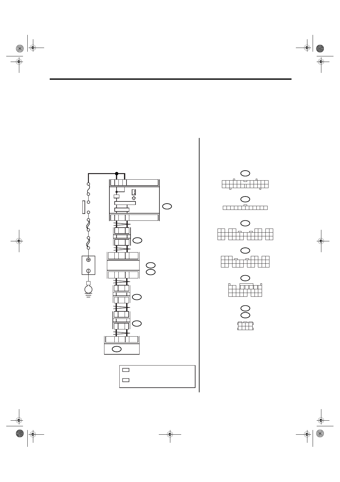
C: CHECK SPORT INDICATOR.
DIAGNOSIS:
Output signal circuit of SPORT indicator is open or shorted.
TROUBLE SYMPTOM:
• SPORT indicator does not display or remains displayed.
• SPORT indicator display does not change.
WIRING DIAGRAM:
• LHD model
AT-03168
3
4
21
1
22
7
i10
i77
2
8
A27
A26
B20
B30
i84
A:
B280
B:
3
12
TCM
B54
i10
i77
i84
B280
B54
2
1
3 4
6 7 8 9 10
22
21
20
19
18
17
16
15
14
13
12
11
5
12
11
10
9
8
7
6
5
4
3
2
1
8
7
6
5
4
3
2
1
22 23
21
20
19
16
15
14
13
12
11
10
9
34 35
33
32
17
30
18
31
29
28
27
26
25
24
8
7
6
5
4
3
2
1
22
23
21
20
19
16
15
14
13
12
11
10
9
17
30
18
29
28
27
26
25
24
8
3
4
5
6
7
2
1
18 19 20
17
16
15
14
13
12
11
10
9
24
23
22
21
E
COMBINATION
METER
SPORT
INDICATOR
JOINT
CONNECTOR
BODY INTEGRATED MODULE
IGNITION
SWITCH
B
A
TTER
Y
A:
B:
2
4
5
7
B352
JOINT
CONNECTOR
B355
JOINT
CONNECTOR
B352
B355
1 2 3 4
5 6 7 8
2
*
2
*
1
*
1
*
No.12
SBF-6
MAIN SBF
1
*
: TERMINAL No. RANDOM ARRANGEMENT
AMONG 1,2,5, AND 6
2
*
: TERMINAL No. RANDOM ARRANGEMENT
AMONG 3,4,7, AND 8
Нет комментариевНе стесняйтесь поделиться с нами вашим ценным мнением.
Текст