Subaru Legacy (2005 year). Service manual — part 570
4AT(diag)-117
AUTOMATIC TRANSMISSION (DIAGNOSTICS)
Diagnostic Procedure with Diagnostic Trouble Code (DTC)
Step
Check
Yes
No
1
CHECK BODY INTEGRATED MODULE.
1) Connect the Subaru Select Monitor to data
link connector.
2) Turn the ignition switch to ON. (engine
OFF)
3) Read the DTC of body integrated module
using Subaru Select Monitor. <Ref. to
LAN(diag)-14, OPERATION, Subaru Select
Monitor.>
Is DTC displayed?
Perform the diag-
nosis according to
DTC.
2
CHECK BODY INTEGRATED MODULE IN-
PUT SIGNAL.
1) Shift the select lever to “P” range.
2) Read the Tiptronic Mode Switch data of
body integrated module using Subaru Select
Monitor. <Ref. to LAN(diag)-14, OPERATION,
Subaru Select Monitor.>
Is OFF displayed?
3
CHECK BODY INTEGRATED MODULE IN-
PUT SIGNAL.
1) Shift the select lever from “P” to “D” range.
2) Read the Tiptronic Mode Switch data of
body integrated module using Subaru Select
Monitor. <Ref. to LAN(diag)-14, OPERATION,
Subaru Select Monitor.>
Is the indication on each range
OFF?
Replace the select
lever assembly.
<Ref. to CS-22,
Select Lever.>
4
CHECK BODY INTEGRATED MODULE IN-
PUT SIGNAL.
1) Shift the select lever to manual mode side.
2) Shift the select lever to any other than “D”
range.
3) Read the Tiptronic Mode Switch data of
body integrated module using Subaru Select
Monitor. <Ref. to LAN(diag)-14, OPERATION,
Subaru Select Monitor.>
Is OFF displayed?
Replace the select
lever assembly.
<Ref. to CS-22,
Select Lever.>
5
CHECK INHIBITOR SWITCH.
Shift the select lever from “P” to “D” range.
Is the indication of range posi-
tion indicator light in combina-
tion meter synchronized with
position of select lever?
Adjust the inhibi-
tor switch and
select cable. <Ref.
to 4AT-51,
ADJUSTMENT,
Inhibitor Switch.>
<Ref. to CS-30,
ADJUSTMENT,
Select Cable.>
6
CHECK TCM INPUT SIGNAL.
1) Shift the select lever from “P” to “D” range.
2) Read the Tiptronic Mode Switch data of
TCM using Subaru Select Monitor. <Ref. to
4AT(diag)-16, OPERATION, Subaru Select
Monitor.>
Is the indication on each range
OFF?
Even if the SPORT
indicator light is
blinking, the cir-
cuit has returned
to normal condi-
tion at this time. A
temporary short
circuit of connector
or harness may be
the cause. Repair
the harness or
connector.
Replace the TCM.
<Ref. to 4AT-66,
Transmission Con-
trol Module
(TCM).>
4AT(diag)-118
AUTOMATIC TRANSMISSION (DIAGNOSTICS)
Diagnostic Procedure with Diagnostic Trouble Code (DTC)
7
CHECK HARNESS BETWEEN BODY INTE-
GRATED MODULE AND SWITCH FOR
SPORT MODE AND MANUAL MODE.
1) Turn the ignition switch to OFF.
2) Disconnect the harness connector from
body integrated module and select lever.
3) Measure the resistance of body integrated
module and chassis ground.
Connector & terminal
(B281) No. 26 — Chassis ground:
Is the resistance more than 1
M
Ω?
Repair the short
circuit of harness
between body inte-
grated module and
switch for SPORT
mode and manual
mode.
8
CHECK SWITCH FOR SPORT MODE AND
MANUAL MODE.
1) Shift the select lever to “P” range.
2) Measure the resistance between connector
terminals of switch for SPORT mode and man-
ual mode.
Terminal
No. 7 — No. 8:
Is the resistance more than 1
M
Ω?
Check the body
integrated module.
Replace the select
lever assembly.
<Ref. to CS-22,
Select Lever.>
Step
Check
Yes
No
4AT(diag)-119
AUTOMATIC TRANSMISSION (DIAGNOSTICS)
Diagnostic Procedure without Diagnostic Trouble Code (DTC)
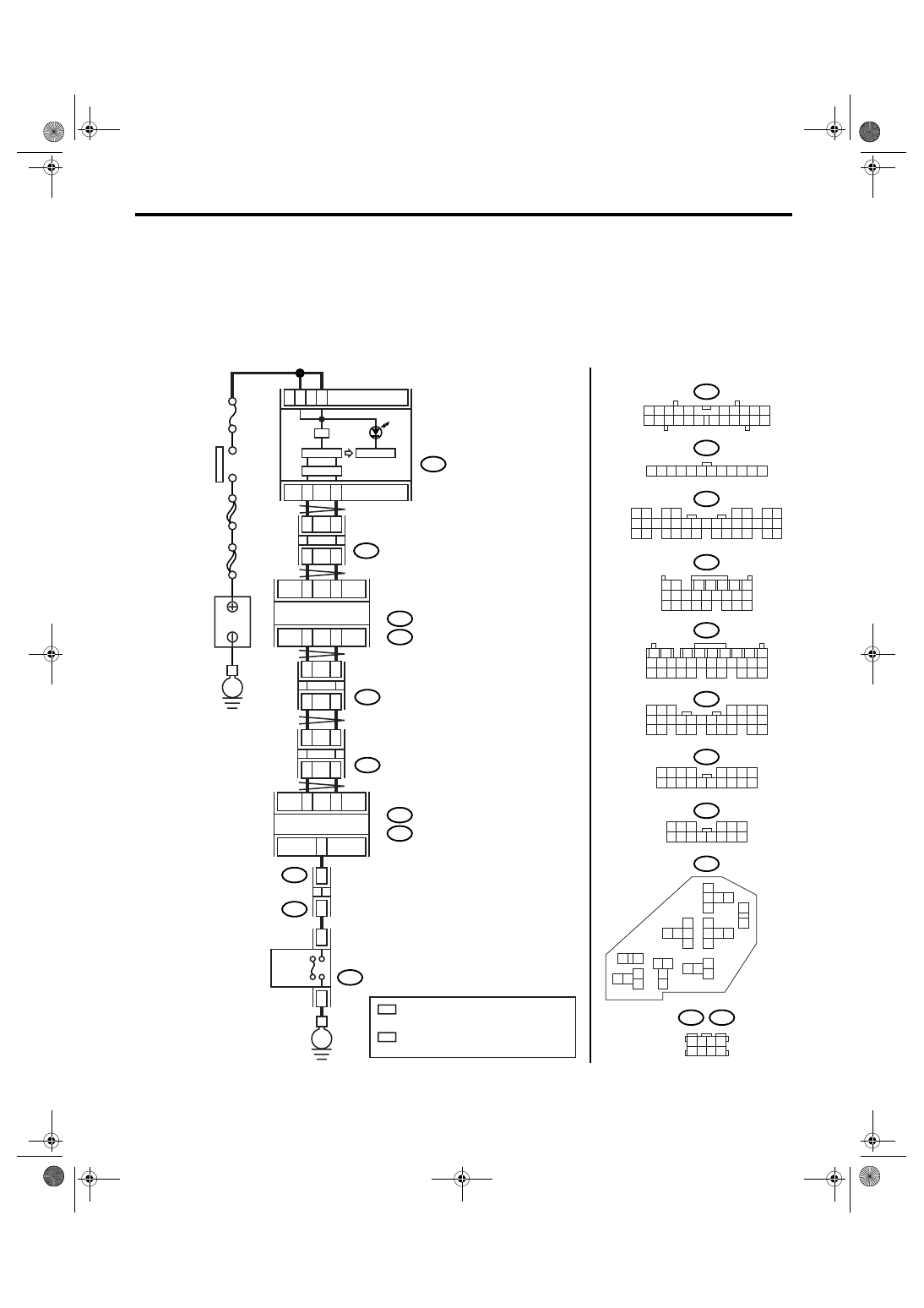
14.Diagnostic Procedure without Diagnostic Trouble Code (DTC)
A: CHECK FWD SWITCH
DIAGNOSIS:
• LED does not come on even if FWD switch is ON.
• FWD signal circuit is open or shorted.
WIRING DIAGRAM:
• LHD model
i10
i77
i84
B54
B281
2
1
3 4
6 7 8 9 10
22
21
20
19
18
17
16
15
14
13
12
11
5
12
11
10
9
8
7
6
5
4
3
2
1
8
7
6
5
4
3
2
1
22 23
21
20
19
16
15
14
13
12
11
10
9
34 35
33
32
17
30
18
31
29
28
27
26
25
24
8
7
6
5
4
3
2
1
22 23
21
20
19
16
15
14
13
12
11
10
9
17 18
28
27
26
25
24
F108
8
7
6
5
4
3
2
1
16
15
14
13
12
11
10
9
17 18
B361
F27
8
7
6
5
4
3
2
1
14
13
12
11
10
9
8
3
4
5
6
7
2
1
18 19 20
17
16
15
14
13
12
11
10
9
24
23
22
21
B55
3
4
1
2
5
6
7
8
9
18 19 20 21
17
16
15
14
13
12
11
10
24
23
22
26
25
28
27
31
30
29
5
4
2
1
3
16 17
14
13
6
7
15
11
9
8
10
12
31
29
28
25
26
27
22
23
21
20
24
19
18
30
A:
B:
A:
B:
AT-03164
3
4
21
1
22
7
i10
i77
2
8
A27
A26
B20
B30
A3
A12
B17
i84
A:
B281
B:
TCM
B54
A:
B55
B:
FWD
SWITCH
F27
B361
F108
19
11
18
13
E
AWD
E
IGNITION
SWITCH
B
A
TTER
Y
COMBINATION
METER
JOINT
CONNECTOR
BODY INTEGRATED MODULE
JOINT
THROUGH
CONNECTOR
A/C RELAY HOLDER
2
4
5
7
B352
JOINT
CONNECTOR
B355
JOINT
CONNECTOR
B352
B355
1 2 3 4
5 6 7 8
No.12
SBF-6
MAIN SBF
2
*
2
*
1
*
1
*
1
*
: TERMINAL No. RANDOM ARRANGEMENT
AMONG 1,2,5, AND 6
2
*
: TERMINAL No. RANDOM ARRANGEMENT
AMONG 3,4,7, AND 8
4AT(diag)-120
AUTOMATIC TRANSMISSION (DIAGNOSTICS)
Diagnostic Procedure without Diagnostic Trouble Code (DTC)
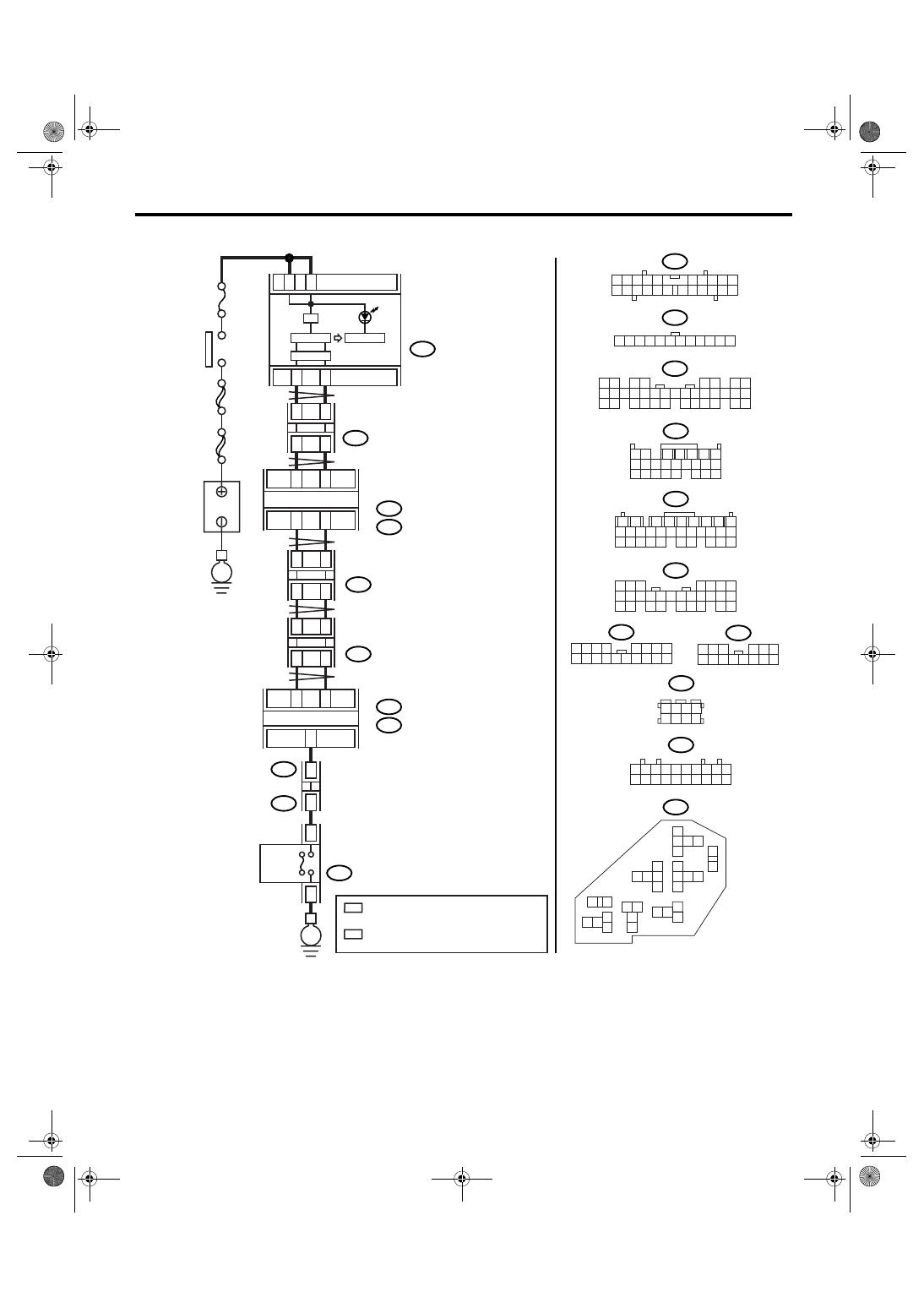
• RHD model
i10
i77
i84
B54
B281
2
1
3 4
6 7 8 9 10
22
21
20
19
18
17
16
15
14
13
12
11
5
12
11
10
9
8
7
6
5
4
3
2
1
8
7
6
5
4
3
2
1
22 23
21
20
19
16
15
14
13
12
11
10
9
34 35
33
32
17
30
18
31
29
28
27
26
25
24
8
7
6
5
4
3
2
1
22 23
21
20
19
16
15
14
13
12
11
10
9
17 18
28
27
26
25
24
F108
8
7
6
5
4
3
2
1
16
15
14
13
12
11
10
9
17 18
B361
F27
8
7
6
5
4
3
2
1
14
13
12
11
10
9
8
3
4
5
6
7
2
1
18 19 20
17
16
15
14
13
12
11
10
9
24
23
22
21
B55
3
4
1
2
5
6
7
8
9
18 19 20 21
17
16
15
14
13
12
11
10
24
23
22
26
25
28
27
31
30
29
5
4
2
1
3
16 17
14
13
6
7
15
11
9
8
10
12
31
29
28
25
26
27
22
23
21
20
24
19
18
30
A:
B:
A:
B:
AT-03165
3
4
21
1
22
7
i10
i77
2
8
A27
A26
B20
B30
A3
A12
B17
i84
A:
B281
B:
TCM
B54
A:
B55
B:
FWD
SWITCH
F27
B361
F108
19
11
18
13
E
AWD
E
IGNITION
SWITCH
B
A
TTER
Y
COMBINATION
METER
JOINT
CONNECTOR
BODY INTEGRATED MODULE
JOINT
THROUGH
CONNECTOR
A/C RELAY HOLDER
8
B352
2
4
B53
JOINT
CONNECTOR
JOINT
CONNECTOR
B352
B53
10
9
8
7
6
5
4
3
2
1
20
19
18
17
16
15
14
13
12
11
2
1
3 4
8
7
6
5
No.12
SBF-6
MAIN SBF
2
*
2
*
1
*
1
*
6
1
*
: TERMINAL No. RANDOM ARRANGEMENT
AMONG 8,18, AND 19
2
*
: TERMINAL No. RANDOM ARRANGEMENT
AMONG 9,10, AND 20
Нет комментариевНе стесняйтесь поделиться с нами вашим ценным мнением.
Текст