Subaru Legacy (2005 year). Service manual — part 569
4AT(diag)-113
AUTOMATIC TRANSMISSION (DIAGNOSTICS)
Diagnostic Procedure with Diagnostic Trouble Code (DTC)
Step
Check
Yes
No
1
CHECK OUTPUT OF LATERAL G SENSOR
USING SUBARU SELECT MONITOR.
1) Select {Current Data Display & Save} in
Subaru Select Monitor.
2) Read the lateral G sensor output on Subaru
Select Monitor display.
Is the value on display 2.3 —
2.7 V when the lateral G sen-
sor is in horizontal position?
2
CHECK POOR CONTACT IN CONNECTOR. Is there poor contact in con-
nector between TCM and lat-
eral G sensor?
Repair the con-
nector.
3
CHECK ABSCM&H/U.
1) Connect all the connectors.
2) Perform the clear memory mode.
3) Perform the inspection mode.
4) Read the DTC.
Is the same DTC still dis-
played?
Replace the TCM.
<Ref. to 4AT-66,
Transmission Con-
trol Module
(TCM).>
4
CHECK ANY OTHER DTC ON DISPLAY.
Is any other DTC displayed?
Perform the diag-
nosis according to
DTC.
Temporary poor
contact occurs.
5
CHECK CONDITIONAL INFORMATION
WHEN FAULTY.
Read the lateral G sensor output on Subaru
Select Monitor display.
Is the reading on monitor dis-
play 4.65 V or more?
6
CHECK OPEN CIRCUIT IN LATERAL G SEN-
SOR OUTPUT HARNESS AND GROUND
HARNESS.
1) Turn the ignition switch to OFF.
2) Disconnect the connector from TCM.
3) Measure the resistance between TCM con-
nector terminals.
Connector & terminal
(B54) No. 2 — No. 9:
Is the resistance 4.3 — 4.9
k
Ω?
Repair the har-
ness connector
between lateral G
sensor and
ABSCM&H/U.
7
CHECK BATTERY SHORT OF HARNESS.
1) Turn the ignition switch to OFF.
2) Remove the console box.
3) Disconnect the connector from lateral G
sensor.
4) Disconnect the connector from TCM.
5) Measure the voltage between TCM con-
nector and chassis ground.
Connector & terminal
(B54) No. 2 (+) — Chassis ground (
−
):
Is the voltage less than 1 V?
Repair the har-
ness between lat-
eral G sensor and
TCM.
8
CHECK BATTERY SHORT OF HARNESS.
1) Turn the ignition switch to ON.
2) Measure the voltage between TCM con-
nector and chassis ground.
Connector & terminal
(B54) No. 2 (+) — Chassis ground (
−
):
Is the voltage less than 1 V?
Repair the har-
ness between lat-
eral G sensor and
TCM.
9
CHECK POOR CONTACT IN CONNECTOR. Is there poor contact in con-
nector between TCM and lat-
eral G sensor?
Repair the con-
nector.
10
CHECK TCM.
1) Connect all the connectors.
2) Perform the clear memory mode.
3) Perform the inspection mode.
4) Read the DTC.
Is the same DTC still dis-
played?
Replace the TCM.
<Ref. to 4AT-66,
Transmission Con-
trol Module
(TCM).>
11
CHECK ANY OTHER DTC ON DISPLAY.
Is any other DTC displayed?
Perform the diag-
nosis according to
DTC.
Temporary poor
contact occurs.
4AT(diag)-114
AUTOMATIC TRANSMISSION (DIAGNOSTICS)
Diagnostic Procedure with Diagnostic Trouble Code (DTC)
12
CHECK INPUT VOLTAGE OF LATERAL G
SENSOR.
1) Turn the ignition switch to OFF.
2) Remove the console box.
3) Remove the lateral G sensor from vehicle.
(Do not disconnect connector.)
4) Turn the ignition switch to ON.
5) Measure the voltage between lateral G
sensor connector terminals.
Connector & terminal
(B359) No. 1 (+) — No. 2 (
−
):
Is the voltage 4.75 — 5.25 V?
Repair the har-
ness connector
between lateral G
sensor and TCM.
13
CHECK OPEN CIRCUIT IN LATERAL G SEN-
SOR OUTPUT HARNESS AND GROUND
HARNESS.
1) Turn the ignition switch to OFF.
2) Disconnect the connector from TCM.
3) Measure the resistance between TCM con-
nector terminals.
Connector & terminal
(B54) No. 2 — No. 9:
Is the resistance 5.0 — 5.6
k
Ω?
Repair the har-
ness connector
between lateral G
sensor and TCM.
14
CHECK LATERAL G SENSOR.
1) Connect the connector to lateral G sensor.
2) Connect the connector to the TCM.
3) Turn the ignition switch to ON.
4) Measure the voltage between lateral G
sensor connector terminals.
Connector & terminal
(B359) No. 3 (+) — No. 2 (
−
):
Is the voltage 2.3 — 2.7 V
when lateral G sensor is hori-
zontal?
Replace the lat-
eral G sensor.
<Ref. to 4AT-67,
Lateral G Sensor.>
15
CHECK LATERAL G SENSOR.
Measure the voltage between lateral G sensor
connector terminals.
Connector & terminal
(B359) No. 3 (+) — No. 2 (
−
):
Is the voltage 3.3 — 4.3 V
when lateral G sensor is
inclined to the right to 90
°?
Replace the lat-
eral G sensor.
<Ref. to 4AT-67,
Lateral G Sensor.>
16
CHECK LATERAL G SENSOR.
Measure the voltage between lateral G sensor
connector terminals.
Connector & terminal
(B359) No. 3 (+) — No. 2 (
−
):
Is the voltage 0.7 — 1.7 V
when lateral G sensor is
inclined to the left to 90
°?
Replace the lat-
eral G sensor.
<Ref. to 4AT-67,
Lateral G Sensor.>
17
CHECK POOR CONTACT IN CONNECTOR.
Turn the ignition switch to OFF.
Is there poor contact in con-
nector between TCM and lat-
eral G sensor?
Repair the con-
nector.
18
CHECK ABSCM&H/U.
1) Connect all the connectors.
2) Perform the clear memory mode.
3) Perform the inspection mode.
4) Read the DTC.
Is the same DTC still dis-
played?
Replace the TCM.
<Ref. to 4AT-66,
Transmission Con-
trol Module
(TCM).>
19
CHECK ANY OTHER DTC ON DISPLAY.
Is any other DTC displayed?
Perform the diag-
nosis according to
DTC.
Temporary poor
contact occurs.
Step
Check
Yes
No
4AT(diag)-115
AUTOMATIC TRANSMISSION (DIAGNOSTICS)
Diagnostic Procedure with Diagnostic Trouble Code (DTC)
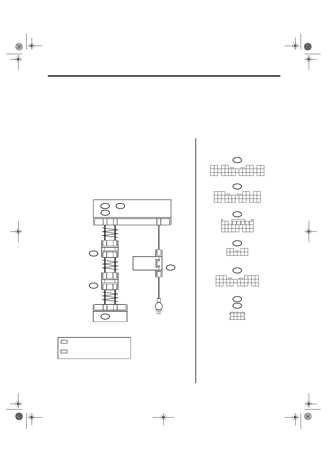
AE:DTC P1817 SPORT MODE SWITCH CIRCUIT
DTC DETECTING CONDITION:
Input signal circuit of SPORT mode and manual mode switch is shorted.
TROUBLE SYMPTOM:
• Manual mode can not be set.
• The SPORT indicator light does not illuminate.
• SPORT mode can not be set.
WIRING DIAGRAM:
• LHD model
AT-03162
i84
B280
B54
B116
B281
10
9
8
7
6
5
4
3
2
1
8
7
6
5
4
3
2
1
22 23
21
20
19
16
15
14
13
12
11
10
9
34 35
33
32
17
30
18
31
29
28
27
26
25
24
8
7
6
5
4
3
2
1
22
23
21
20
19
16
15
14
13
12
11
10
9
17
30
18
29
28
27
26
25
24
8
7
6
5
4
3
2
1
22 23
21
20
19
16
15
14
13
12
11
10
9
17 18
28
27
26
25
24
8
3
4
5
6
7
2
1
18 19 20
17
16
15
14
13
12
11
10
9
24
23
22
21
A:
B:
C:
B352
B355
1 2 3 4
5 6 7 8
C26
B116
8
7
i84
A:
B280
B:
B281
C:
B20
B30
E
BODY INTEGRATED MODULE
SELECT
LEVER
3
12
TCM
B54
2
4
5
7
B352
JOINT
CONNECTOR
B355
JOINT
CONNECTOR
2
*
2
*
1
*
1
*
1
*
: TERMINAL No. RANDOM ARRANGEMENT
AMONG 1,2,5, AND 6
2
*
: TERMINAL No. RANDOM ARRANGEMENT
AMONG 3,4,7, AND 8
SPORT MODE
AND MANUAL
MODE SWITCH
4AT(diag)-116
AUTOMATIC TRANSMISSION (DIAGNOSTICS)
Diagnostic Procedure with Diagnostic Trouble Code (DTC)
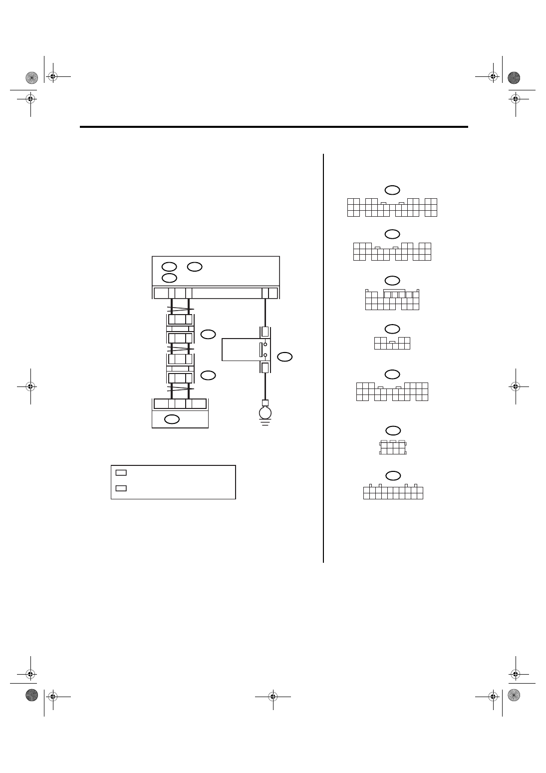
• RHD model
AT-03163
i84
B280
B54
B116
B281
10
9
8
7
6
5
4
3
2
1
8
7
6
5
4
3
2
1
22 23
21
20
19
16
15
14
13
12
11
10
9
34 35
33
32
17
30
18
31
29
28
27
26
25
24
8
7
6
5
4
3
2
1
22
23
21
20
19
16
15
14
13
12
11
10
9
17
30
18
29
28
27
26
25
24
8
7
6
5
4
3
2
1
22 23
21
20
19
16
15
14
13
12
11
10
9
17 18
28
27
26
25
24
8
3
4
5
6
7
2
1
18 19 20
17
16
15
14
13
12
11
10
9
24
23
22
21
A:
B:
C:
C26
B116
8
7
i84
A:
B280
B:
B281
C:
B20
B30
E
3
12
B54
BODY INTEGRATED MODULE
SELECT
LEVER
TCM
8
B352
2
4
B53
JOINT
CONNECTOR
JOINT
CONNECTOR
B352
B53
10
9
8
7
6
5
4
3
2
1
20
19
18
17
16
15
14
13
12
11
2
1
3 4
8
7
6
5
2
*
2
*
1
*
1
*
6
1
*
: TERMINAL No. RANDOM ARRANGEMENT
AMONG 8,18, AND 19
2
*
: TERMINAL No. RANDOM ARRANGEMENT
AMONG 9,10, AND 20
SPORT MODE
AND MANUAL
MODE SWITCH
Нет комментариевНе стесняйтесь поделиться с нами вашим ценным мнением.
Текст