Subaru Legacy (2005 year). Service manual — part 495
CS-21
CONTROL SYSTEMS
AT Shift Lock Control System
8
CHECK HARNESS BETWEEN “P” RANGE
SWITCH AND CHASSIS GROUND.
Measure the resistance of harness between
“P” range switch and chassis ground.
Connector & terminal
(B116) No. 1 — Chassis ground:
Is the resistance less than 1
Ω?
Repair short circuit
of the harness
between “P” range
switch and body
integrated module.
9
CHECK HARNESS BETWEEN BODY INTE-
GRATED MODULE AND “P” RANGE
SWITCH.
1) Disconnect the connector of “P” range
switch.
2) Measure the resistance of harness
between body integrated module and “P”
range switch.
Connector & terminal
(B116) No. 1 — (B281) No. 13:
Is the resistance more than 1
M
Ω?
Repair open circuit
of the harness
between body inte-
grated module and
“P” range switch.
10
CHECK HARNESS BETWEEN “P” RANGE
SWITCH AND CHASSIS GROUND.
Measure the resistance of harness between
“P” range switch and chassis ground.
Connector & terminal
(B116) No. 2 — Chassis ground:
Is the resistance more than 1
M
Ω?
Repair open circuit
in the harness
between “P” range
switch and chas-
sis ground.
11
CHECK “P” RANGE SWITCH.
1) Shift the select lever to “P” range.
2) Measure the resistance between “P” range
switch connector terminals.
Terminal
No. 2 — No. 1:
Is the resistance less than 1
Ω?
Replace the “P”
range switch.
12
CHECK “P” RANGE SWITCH.
1) Shift the select lever to other than “P”
range.
2) Measure the resistance between “P” range
switch connector terminals.
Terminal
No. 2 — No. 1:
Is the resistance more than 1
M
Ω?
Replace the “P”
range switch.
13
CHECK OPERATION.
1) Connect all the connectors.
2) Operate the key lock solenoid.
Does the key lock solenoid
operate normally?
A temporary poor
contact of connec-
tor or harness may
be the cause.
Check the body
integrated module.
Step
Check
Yes
No
CS-22
CONTROL SYSTEMS
Select Lever
3. Select Lever
A: REMOVAL
1) Set the vehicle on a lift.
2) Disconnect the ground cable from battery.
3) Shift the select lever to “N” range.
4) Lift-up the vehicle.
5) Remove the rear exhaust pipe and muffler.
• SOHC model
<Ref. to EX(H4SO 2.0)-10, REMOVAL, Rear Ex-
haust Pipe.> <Ref. to EX(H4SO 2.0)-12, REMOV-
AL, Muffler.>
• DOHC non-turbo model
<Ref. to EX(H6DO)-7, REMOVAL, Rear Exhaust
Pipe.> <Ref. to EX(H6DO)-9, REMOVAL, Muffler.>
• DOHC turbo model
<Ref. to EX(H4DOTC)-11, REMOVAL, Rear Ex-
haust Pipe.> <Ref. to EX(H4DOTC)-12, REMOV-
AL, Muffler.>
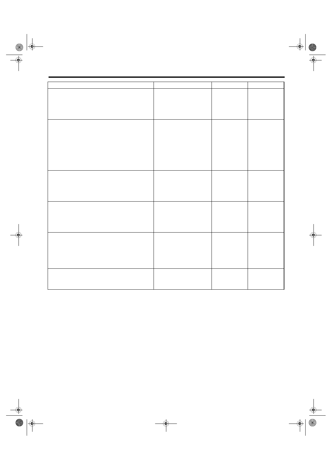
6) Remove the heat shield cover.
7) Remove the select cable from arm assembly.
8) Raise the pawl of clamp to remove the select ca-
ble.
9) Lower the vehicle.
10) Remove the console box. <Ref. to EI-53, RE-
MOVAL, Console Box.>
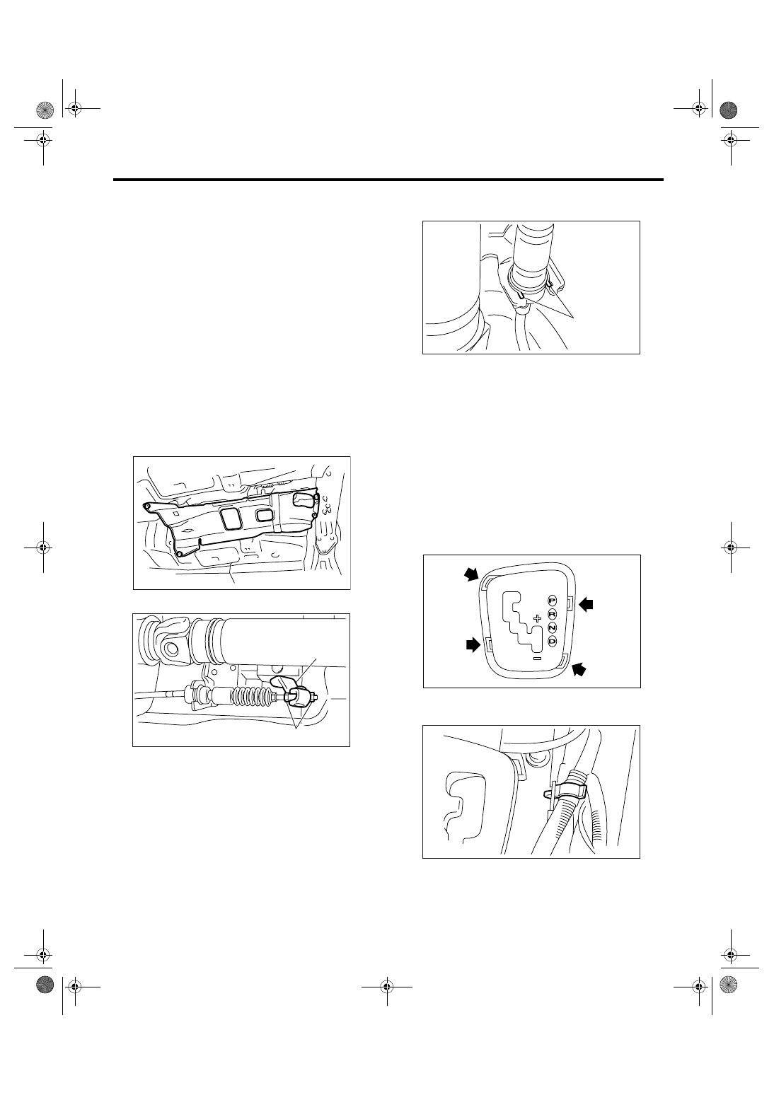
11) Remove the ring indicator.
Insert the tip of a flap tip screwdriver into the gap
between ring indicator and console front panel, and
lift up gradually.
NOTE:
• Wrap the tip of a flat tip screwdriver with cloth.
• Insert the tip of a flat tip screwdriver into four
pawls, and remove the ring indicator equally and
gradually.
12) Remove the console front panel.
13) Remove the harness clips from bracket.
(A) Adjusting nut
(B) Arm ASSY
AT-01331
(B)
CS-00278
(A)
(A) Pawl
CS-00279
(A)
CS-00583
CS-00372
CS-23
CONTROL SYSTEMS
Select Lever
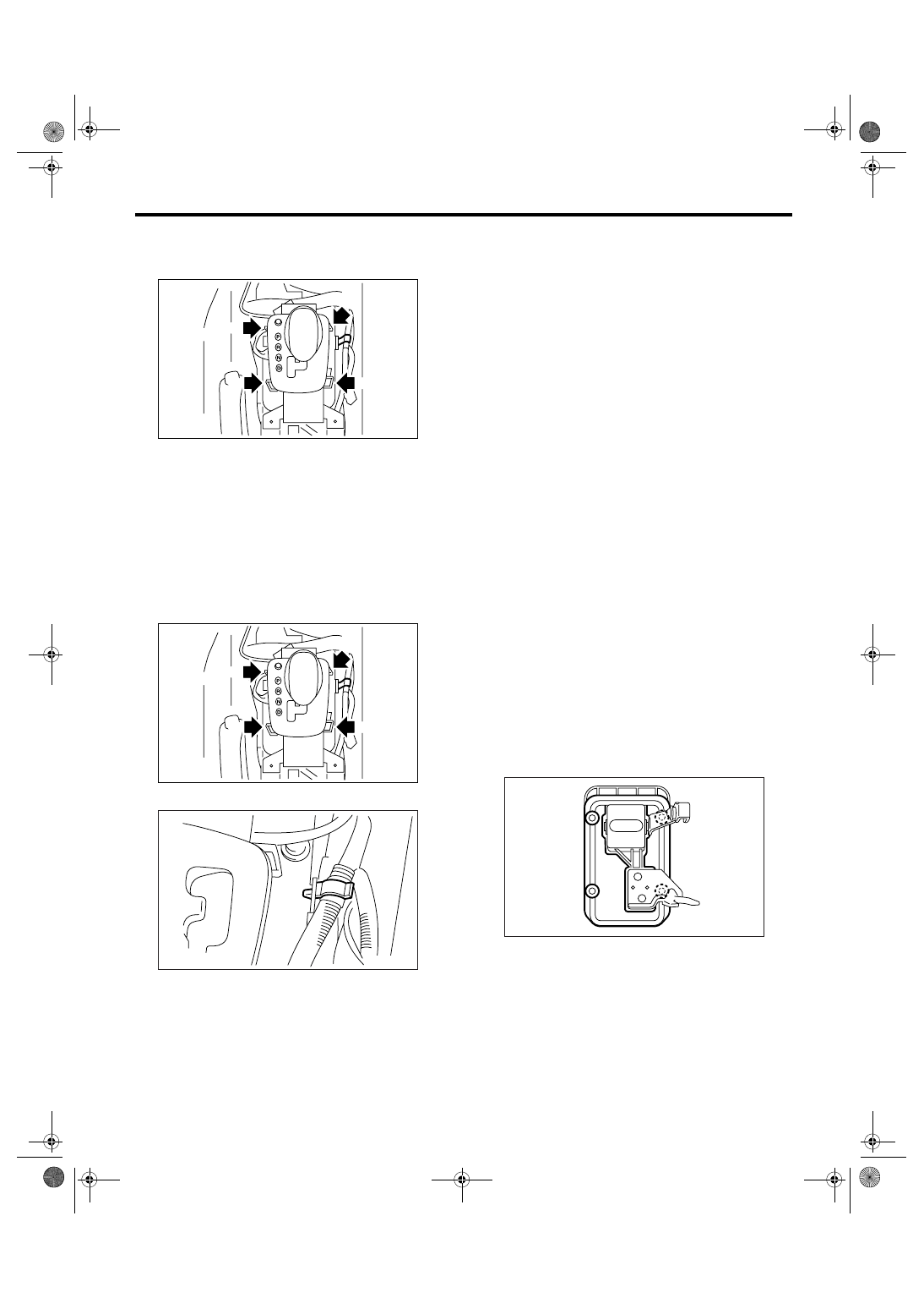
14) Disconnect the connectors, and then remove
the four bolts to take out the select lever assembly
from vehicle body.
B: INSTALLATION
1) Set the select lever assembly to vehicle body.
2) Tighten the four bolts to install the select lever to
vehicle body, and then connect the connector.
(1) Temporarily tighten the bolt A.
(2) Tighten the bolt B.
(3) Tighten the bolt A.
(4) Tighten the bolts C and D.
Tightening torque:
18 N
⋅
m (1.8 kgf-m, 13.3 ft-lb)
3) Install the harness clips to the bracket.
4) Install the console front panel.
5) Install the ring indicator.
6) Install the console box. <Ref. to EI-53, INSTAL-
LATION, Console Box.>
7) Shift the select lever to “N” range.
8) Lift-up the vehicle.
9) Fix the select cable to bracket. <Ref. to CS-28,
INSTALLATION, Select Cable.>
10) Adjust the select cable position. <Ref. to CS-
30, ADJUSTMENT, Select Cable.>
11) After the completion of adjustment, confirm that
the select lever operates properly at all range posi-
tions.
12) Install the heat shield cover.
13) Install the rear exhaust pipe and muffler.
• SOHC model
<Ref. to EX(H4SO 2.0)-10, INSTALLATION, Rear
Exhaust Pipe.> <Ref. to EX(H4SO 2.0)-12, IN-
STALLATION, Muffler.>
• DOHC non-turbo model
<Ref. to EX(H6DO)-7, INSTALLATION, Rear Ex-
haust Pipe.> <Ref. to EX(H6DO)-9, INSTALLA-
TION, Muffler.>
• DOHC turbo model
<Ref. to EX(H4DOTC)-11, INSTALLATION, Rear
Exhaust Pipe.> <Ref. to EX(H4DOTC)-12, IN-
STALLATION, Muffler.>
14) Inspect the following items. When the malfunc-
tions are found in the inspection, adjust the select
cable and inhibitor switch.
NOTE:
Inhibitor switch for 5AT model is not adjustable.
<Ref. to CS-30, ADJUSTMENT, Select Cable.>
<Ref. to 4AT-51, ADJUSTMENT, Inhibitor Switch.>
(1) Engine starts when the select lever is in “P”
and “N” range, but not in other range.
(2) Back-up light illuminates when the select le-
ver is in the “R” range, but not in other range.
(3) Select lever and indicator positions are
matched.
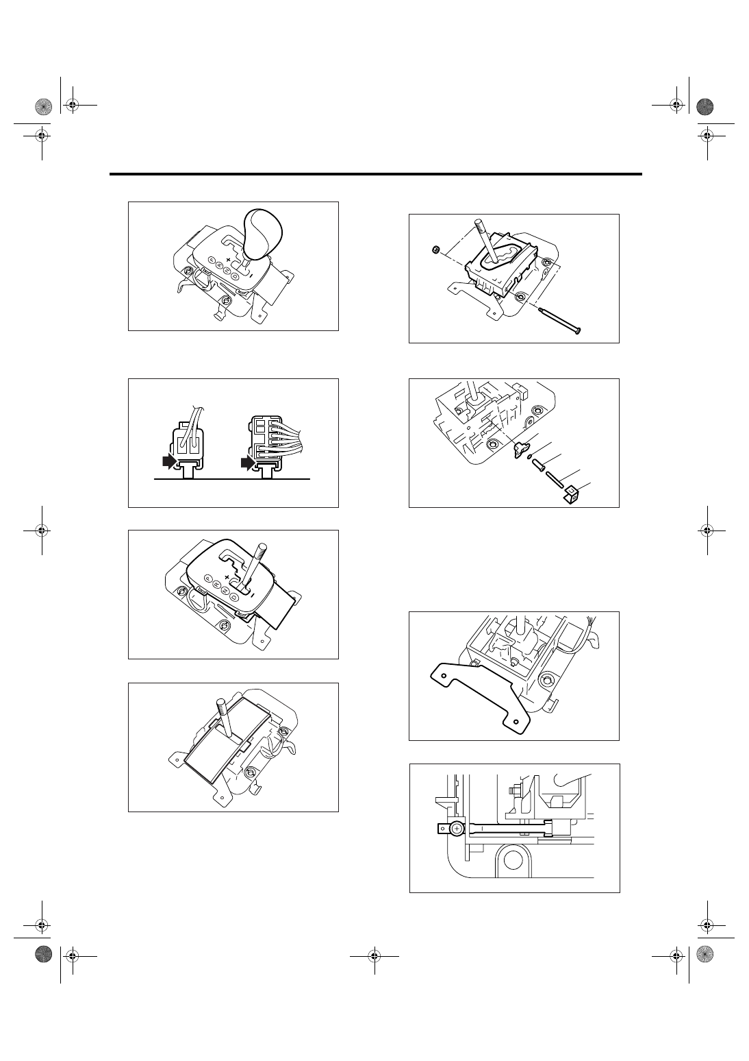
C: DISASSEMBLY
1) Remove the packing and plate.
CS-00580
D
B
A
C
CS-00580
D
B
A
C
CS-00372
CS-00281
CS-24
CONTROL SYSTEMS
Select Lever
2) Remove the grip.
3) Insert a flat-tip screwdriver with thin tip under the
connector to disconnect each connector from the
plate assembly.
4) Remove the indicator cover.
5) Remove the blind.
6) Remove the bolts, and then remove the guide
plate.
7) Remove the clamp, spring A, rod, cushion and
bushing.
8) Remove the bracket.
9) Remove the detent spring.
CS-00557
CS-00375
CS-00558
CS-00285
(A) Clamp
(B) Spring A
(C) Rod
(D) Cushion
(E) Bushing
CS-00377
CS-00378
(A)
(B)
(D)
(C)
(E)
CS-00288
CS-00379
Нет комментариевНе стесняйтесь поделиться с нами вашим ценным мнением.
Текст