Subaru Legacy (2005 year). Service manual — part 496
CS-25
CONTROL SYSTEMS
Select Lever
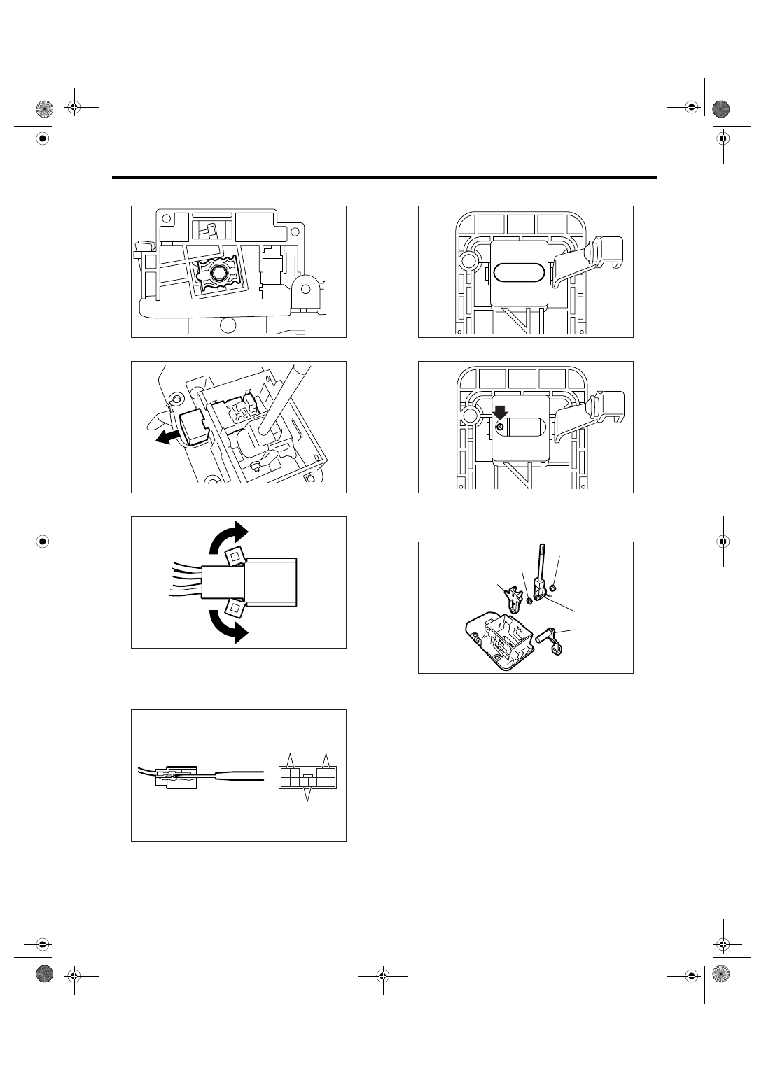
10) Remove the detent plate.
11) Remove the shift lock solenoid unit.
12) Raise the pawl of connector.
13) Use a flat-tip screwdriver with thin tip to discon-
nect the connectors from terminals of SPORT
mode switch, “P” range switch and shift lock sole-
noid unit.
14) Remove the grommet.
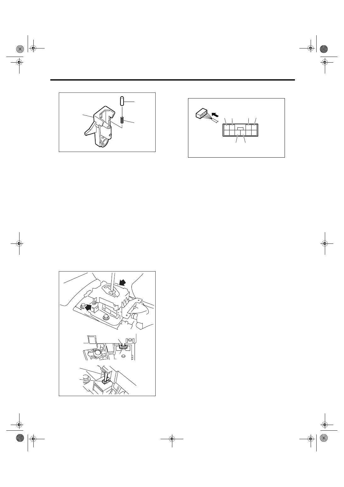
15) Remove the spring pin.
16) Pull out the arm assembly, and then remove
the select lever assembly to remove the arm and
bushing.
(A) “P” range switch terminal
(B) Shift lock solenoid terminal
(C) SPORT mode switch terminal
CS-00380
CS-00381
CS-00292
CS-00293
4
10
3
9 8 7
2 1
6 5
(B)
(A)
(C)
(A) Arm ASSY
(B) Select lever ASSY
(C) Arm
(D) Bushing
CS-00296
CS-00297
CS-00298
(A)
(B)
(C)
(D)
(D)
CS-26
CONTROL SYSTEMS
Select Lever
17) Remove the rod and spring from arm.
D: ASSEMBLY
1) Clean all the parts before assembly.
2) Apply grease [KOPR-KOTE (Part No.
003603001) or equivalent] to each parts. <Ref. to
CS-3, AT SELECT LEVER, COMPONENT, Gener-
al Description.>
3) Assemble in the reverse order of disassembly.
NOTE:
• When installing the guide plate, shift the select
lever to “D” range (normal mode position), care
should be taken in the following points.
(1) Insert the protrusion (B) of guide plate into
the hole of shift lock solenoid unit (A).
(2) Insert the link (D) of shift lock release into
the link (C) of shift lock solenoid unit.
• Connect the switch and solenoid terminal to con-
nector.
4) After completion of installation, shift the select
lever from “P” range to “D” range, then check
whether the indicator and select lever matches,
whether the pointer and position mark matches and
what the operating force is.
E: INSPECTION
1) Inspect the removed parts by comparing with
new ones for deformation, damage and wear. Re-
pair or replace if defective.
2) Confirm the select lever operating condition be-
fore assembly. Normal if it operates smoothly.
(A) Rod
(B) Spring
(C) Arm
CS-00383
(C)
(A)
(B)
CS-00384
b
(D)
(C)
(B)
a
a
b
(A)
(A) “P” range switch (Color code: Red)
(B) “P” range switch (Color code: Red)
(C) Shift lock solenoid (Color code: Black)
(D) Shift lock solenoid (Color code: Blue and Red)
(E) SPORT mode switch (Color code: White)
(F) SPORT mode switch (Color code: Black)
CS-00386
(D)
3
4
9 10
1
2
6
5
7
8
(C)
(E)
(F)
(B) (A)
CS-27
CONTROL SYSTEMS
Select Cable
4. Select Cable
A: REMOVAL
1) Set the vehicle on a lift.
2) Shift the select lever to “N” range.
3) Disconnect the ground cable from battery.
4) Lift-up the vehicle.
5) Remove the front, center and rear exhaust pipes
and muffler. (SOHC and DOHC non-turbo model)
• SOHC model
<Ref. to EX(H4SO 2.0)-6, REMOVAL, Front Ex-
haust Pipe.> <Ref. to EX(H4SO 2.0)-9, REMOVAL,
Center Exhaust Pipe.> <Ref. to EX(H4SO 2.0)-10,
REMOVAL, Rear Exhaust Pipe.> <Ref. to
EX(H4SO 2.0)-12, REMOVAL, Muffler.>
• DOHC non-turbo model
<Ref. to EX(H6DO)-4, REMOVAL, Front Exhaust
Pipe.> <Ref. to EX(H6DO)-7, REMOVAL, Rear Ex-
haust Pipe.> <Ref. to EX(H6DO)-9, REMOVAL,
Muffler.>
6) Remove the center exhaust pipe, rear exhaust
pipe and muffler. (DOHC turbo model)
<Ref. to EX(H4DOTC)-6, REMOVAL, Center Ex-
haust Pipe.> <Ref. to EX(H4DOTC)-11, REMOV-
AL, Rear Exhaust Pipe.> <Ref. to EX(H4DOTC)-
12, REMOVAL, Muffler.>
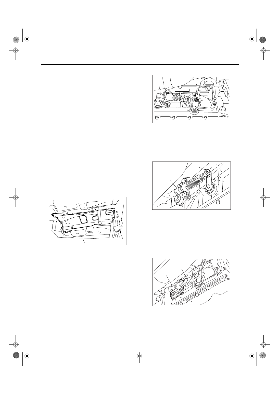
7) Remove the heat shield cover.
8) Remove the snap pin and washer from range se-
lect lever.
• 4AT
• 5AT
9) Remove the plate assembly from transmission
case.
• 4AT
AT-01331
(A) Range select lever
(B) Snap pin
(C) Select cable
(D) Bracket
(E) Washer
(A) Range select lever
(B) Snap pin
(C) Select cable
(D) Bracket
(E) Washer
(A) Select cable
(B) Plate ASSY
(C) Bracket
CS-00036
(C)
(B)
(A)
(E)
(D)
CS-00327
(B)
(D)
(C)
(E)
(A)
CS-00037
( A )
( B )
( C )
CS-28
CONTROL SYSTEMS
Select Cable
• 5AT
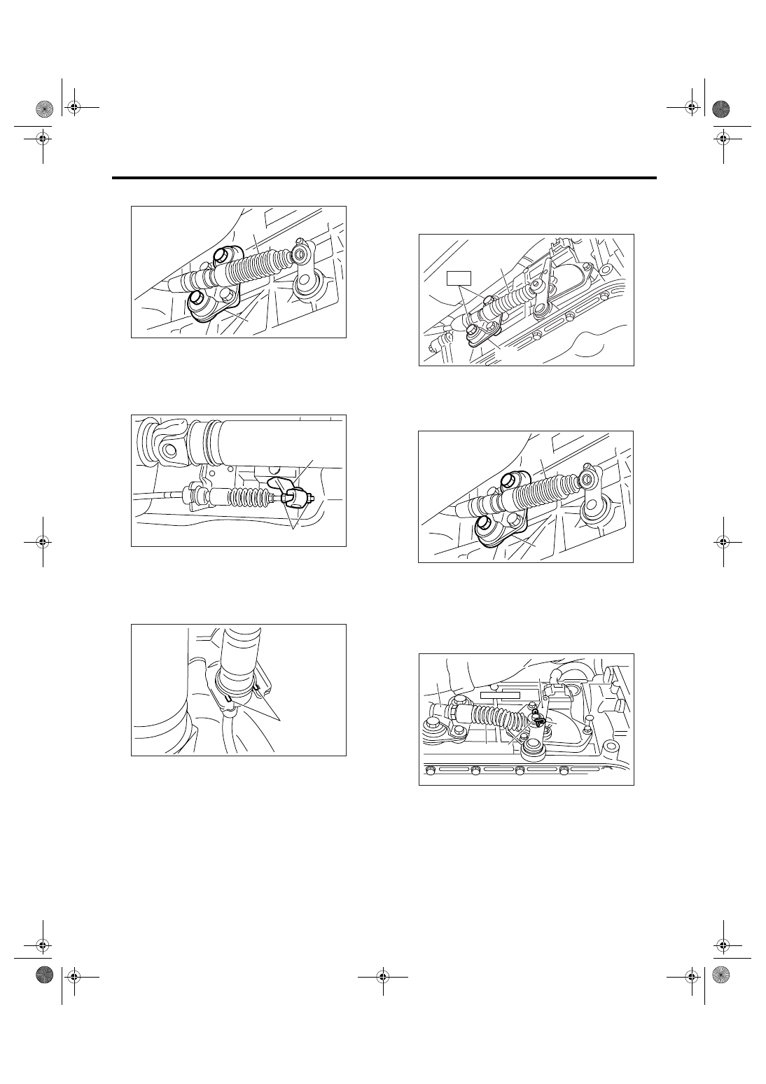
10) Disconnect the select cable from arm assem-
bly.
11) Raise the pawl of clamp to remove the cable
from bracket.
12) Remove the select cable from plate assembly.
B: INSTALLATION
1) Install the select cable to plate assembly.
Tightening torque:
18 N
⋅
m (1.8 kgf-m, 13.3 ft-lb)
2) Install the select cable to range select lever.
3) Install the plate assembly to transmission.
Tightening torque:
25 N
⋅
m (2.5 kgf-m, 18.4 ft-lb)
• 4AT
• 5AT
4) Install the washer and snap pin to range select
lever.
• 4AT
(A) Select cable
(B) Plate ASSY
(A) Adjusting nut
(B) Arm ASSY
(A) Pawl
(A)
(B)
CS-00328
(B)
CS-00278
(A)
CS-00279
(A)
(A) Select cable
(B) Plate ASSY
(A) Select cable
(B) Plate ASSY
(A) Range select lever
(B) Snap pin
(C) Select cable
(D) Bracket
(E) Washer
CS-00039
(A)
(B)
T
(A)
(B)
CS-00328
CS-00036
(C)
(B)
(A)
(E)
(D)
Нет комментариевНе стесняйтесь поделиться с нами вашим ценным мнением.
Текст