Subaru Legacy (2005 year). Service manual — part 493
CS-13
CONTROL SYSTEMS
AT Shift Lock Control System
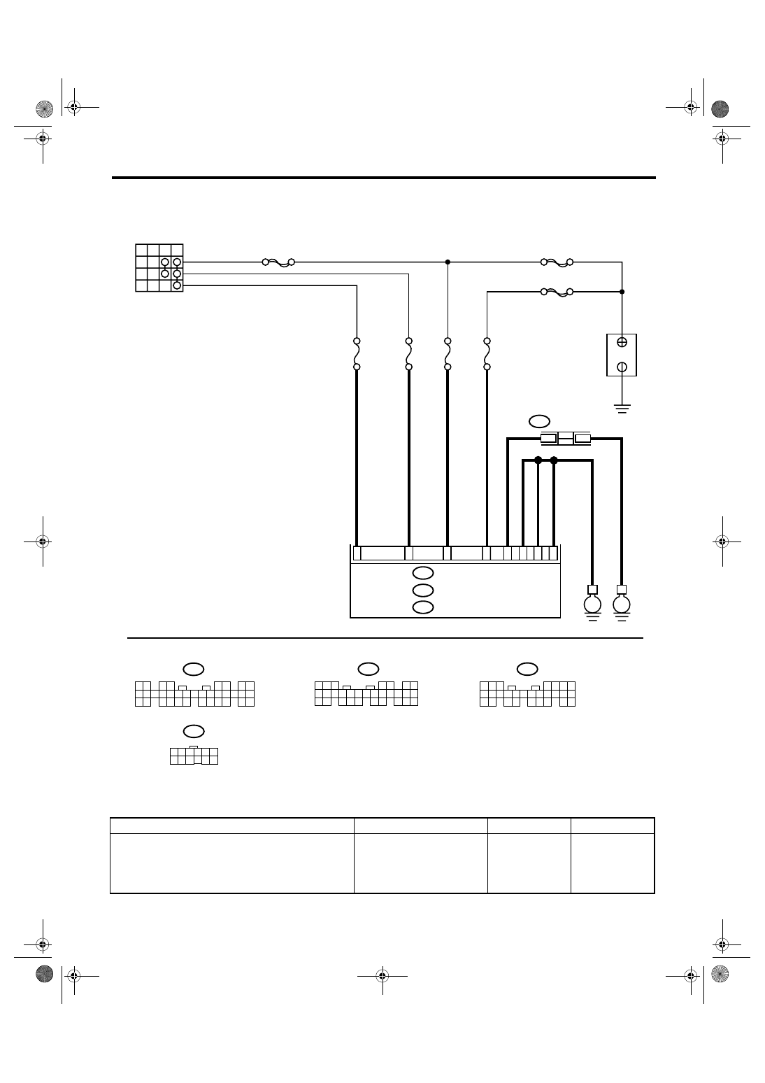
2. BODY INTEGRATED MODULE POWER SUPPLY AND GROUND CIRCUIT
Step
Check
Yes
No
1
CHECK DTC OF BODY INTEGRATED MOD-
ULE.
Check DTC of body integrated module.
<Ref. to LAN(diag)-14, OPERATION, Subaru
Select Monitor.>
Is the DTC of power line dis-
played on body integrated
module?
Repair or replace it
according to the
DTC.
CS-00562
OFF ACC
ACC
ON
B
IG
MAIN SBF
SBF-8
No.12
B281
C:
B280
B:
A1
C2
C8
C9
E
No.7
B7
No.8
SBF-6
i84
A:
No.31
A24
B22
A21
5 6 7
8
2
1
9
4
3
10
24
22 23
25
11 12 13 14 15
26
27 28
16 17 18 19
20 21
5
4
6 7
8
2
1
9
3
10
22
23
11 12 13 14 15
24 25
26 27
16 17 18
28 29
19 20
21
30
1 2
3 4
5 6
7 8
9 10 11 12 13 14 15 16 17 18 19 20 21 22 23
24 25
26 27 28 29
30 31 32 33
34 35
B281
C:
B280
B:
i84
A:
IGNITION SWITCH
BATTERY
JOINT EARTH
CONNECTOR
BODY INTEGRATED MODULE
E
i97
1
2
i97
10 11 12
1 2 3 4 5 6
7 8 9
CS-14
CONTROL SYSTEMS
AT Shift Lock Control System
2
CHECK HARNESS CONNECTOR BETWEEN
BODY INTEGRATED MODULE AND CHAS-
SIS GROUND.
1) Turn the ignition switch to OFF.
2) Measure the harness resistance between
body integrated module and chassis ground.
Connector & terminal
(i84) No. 21 — Chassis ground:
(B280) No. 22 — Chassis ground:
(B281) No. 8 — Chassis ground:
(B281) No. 9 — Chassis ground:
Is the resistance less than 1
Ω?
Repair open circuit
of the harness
between body inte-
grated module and
chassis ground.
3
CHECK FOR POOR CONTACT.
Is there poor contact in con-
nector?
Repair the poor
contact.
Check the body
integrated module.
Step
Check
Yes
No
CS-15
CONTROL SYSTEMS
AT Shift Lock Control System
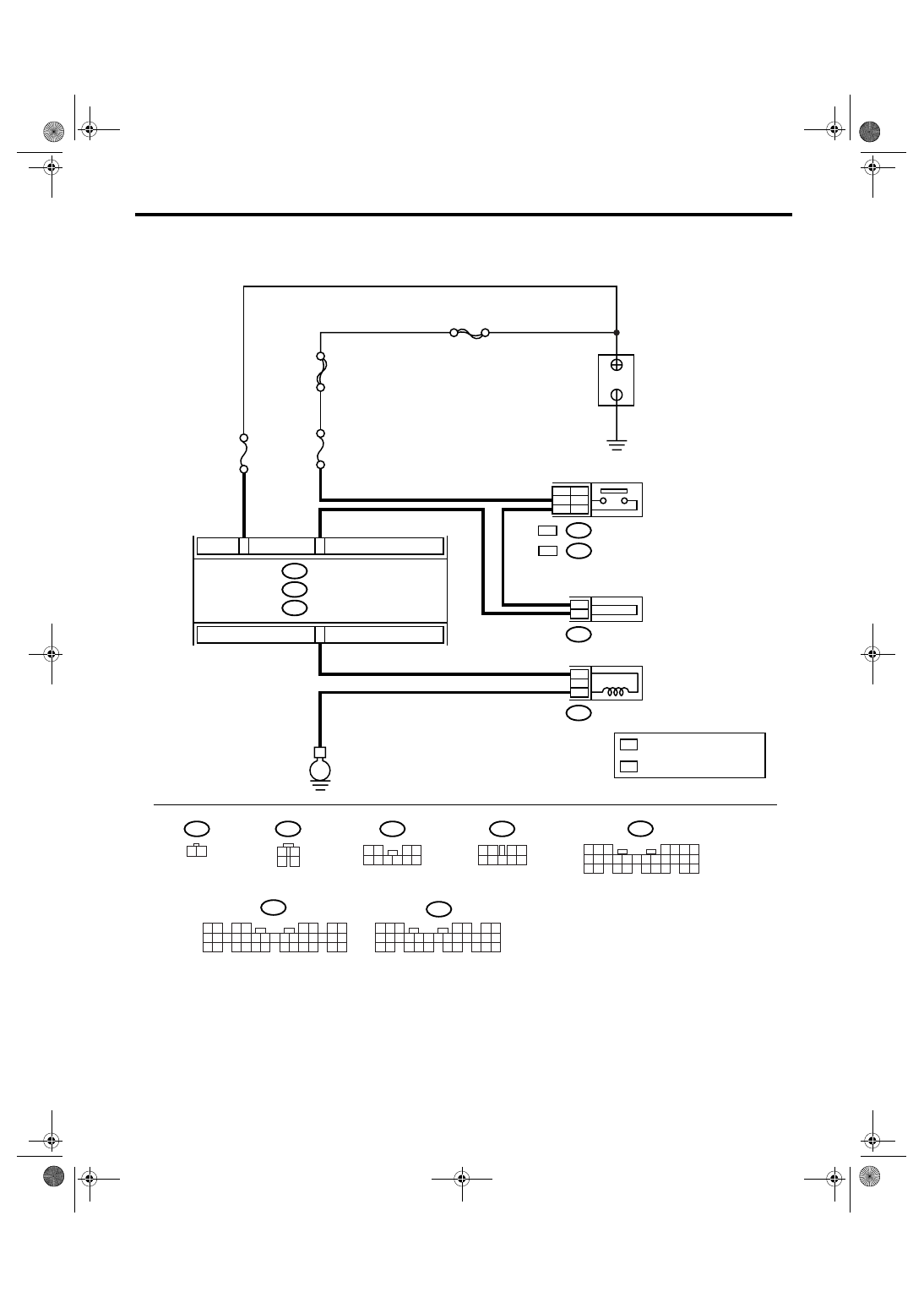
3. SELECT LEVER CANNOT BE SHIFTED
B281
C:
i84
A:
CS-00553
MAIN SBF
SBF-2
No.8
E
B281
C:
B280
B:
i84
A:
C23
B6
B159
5
9
B116
4
3
3
2
2
1
WC
OC
B64
:
B65
OC
WC :
B64
B116
1 2
1
2
3
4
B65
1 2
3 4
5 6 7 8 9 10
5 6 7
8
2
1
9
4
3
10
24
22 23
25
11 12 13 14 15
26
27 28
16 17 18 19
20 21
1 2
3 4
5 6
7 8
9 10 11 12 13 14 15 16 17 18 19 20 21 22 23
24 25
26 27 28 29
30 31 32 33
34 35
1 2
3 4
5 6 7 8 9
B159
C1
No.14
OC
WC
BODY INTEGRATED MODULE
BATTERY
STOP LIGHT SWITCH
SHIFT LOCK SOLENOID
JOINT FUSE BOX
: WITHOUT CRUISE CONTROL
: WITH CRUISE CONTROL
5
4
6 7
8
2
1
9
3
10
22
23
11 12 13 14 15
24 25
26 27
16 17 18
28 29
19 20
21
30
B280
B:

CS-16
CONTROL SYSTEMS
AT Shift Lock Control System
Step
Check
Yes
No
1
CHECK INPUT SIGNAL OF BODY INTE-
GRATED MODULE USING SUBARU SE-
LECT MONITOR.
1) Turn the ignition switch to OFF.
2) Connect the Subaru Select Monitor to data
link connector.
3) Turn the ignition switch and Subaru Select
Monitor power switch to ON.
4) Depress the brake pedal.
5) Read the input signal of stop light switch
from Subaru Select Monitor.
<Ref. to LAN(diag)-14, OPERATION, Subaru
Select Monitor.>
Is “ON” displayed?
2
CHECK DTC OF BODY INTEGRATED MOD-
ULE.
Check DTC of body integrated module.
<Ref. to LAN(diag)-24, OPERATION, Read
Diagnostic Trouble Code (DTC).>
Is DTC (B0106) displayed?
Repair or replace it
according to the
DTC.
3
CHECK STOP LIGHT SWITCH.
Depress the brake pedal.
Does the stop light illuminate? Go to step 4.
Check the stop
light system.
4
CHECK HARNESS BETWEEN STOP LIGHT
SWITCH AND BODY INTEGRATED MOD-
ULE.
1) Turn the ignition switch to OFF.
2) Disconnect the connectors of body inte-
grated module and stop light switch.
3) Measure the resistance of harness
between stop light switch and body integrated
module.
Connector & terminal
Without cruise control
(B64) No. 2 — (B281) No. 23:
With cruise control
(B65) No. 3 — (B281) No. 23:
Is the resistance more than 1
M
Ω?
Repair open circuit
of the harness
between body inte-
grated module and
stop light switch.
5
CHECK HARNESS BETWEEN STOP LIGHT
SWITCH AND BODY INTEGRATED MOD-
ULE.
Measure the resistance of harness between
stop light switch and chassis ground.
Connector & terminal
Without cruise control
(B64) No. 2 — Chassis ground:
With cruise control
(B65) No. 3 — Chassis ground:
Is the resistance less than 1
Ω?
Repair short circuit
of the harness
between body inte-
grated module and
stop light switch.
6
CHECK SHIFT LOCK SOLENOID.
1) Disconnect the connector of shift lock sole-
noid.
2) Connect the battery to connector terminal
of shift lock solenoid, and operate the solenoid.
Terminal
No. 3 (+) — No. 4 (
−
):
Is the shift lock solenoid oper-
ating properly?
Replace the shift
lock solenoid.
7
CHECK SHIFT LOCK OPERATION.
1) Connect all the connectors.
2) Shift the select lever to “P” range.
3) Shift the select lever from “P” range to “R”
range.
Can the select lever shift from
“P” range to “R” range?
Check the body
integrated module.
A temporary poor
contact of connec-
tor or harness may
be the cause.
Нет комментариевНе стесняйтесь поделиться с нами вашим ценным мнением.
Текст