Subaru Legacy (2005 year). Service manual — part 494
CS-17
CONTROL SYSTEMS
AT Shift Lock Control System
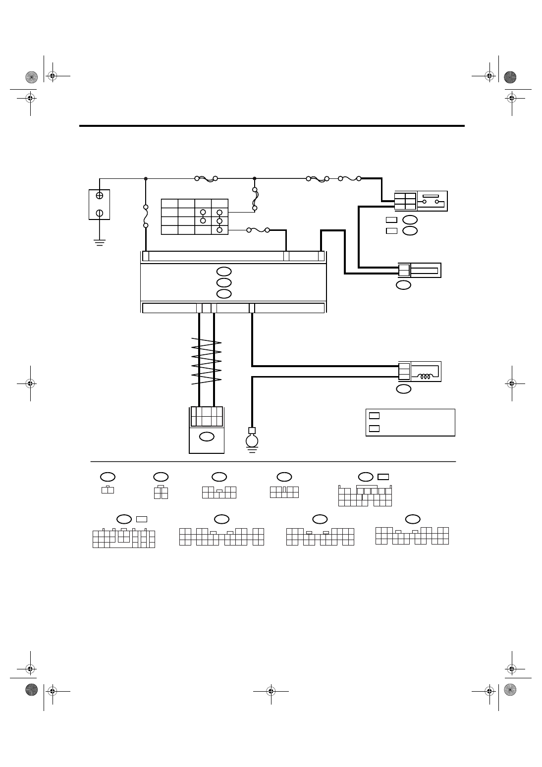
4. SHIFT LOCK OF SELECT LEVER CANNOT BE RELEASED
CS-00554
No.8
E
B280
B:
B281
C:
C23
C1
B6
B
ACC
IG
ACC
OFF
ON
A1
No.12
SBF-2
MAIN SBF
SBF-6
B159
5
9
B116
4
3
B64
:
B65
OC
WC :
B30
B20
B64
B116
1 2
1
2
3
4
B65
1 2
3 4
5 6 7 8 9 10
B159
1 2
3 4
5 6 7 8 9
5 6 7
8
2
1
9
4
3
10
24
22 23
25
11 12 13 14 15
26
27 28
16 17 18 19
20 21
B281
5
4
6 7
8
2
1
9
3
10
22
23
11 12 13 14 15
24 25
26 27
16 17 18
28 29
19 20
21
30
B280
i84
1 2
3 4
5 6
7 8
9 10 11 12 13 14 15 16 17 18 19 20 21 22 23
24 25
26 27 28 29
30 31 32 33
34 35
i84
A:
: WITHOUT CRUISE CONTROL
OC
WC
B54
1 2
7
8 9
5
6
3
4
10 11 12
19 20 21
13 14 15 16
17 18
22 23 24
1 2
7
8
9
5 6
3 4
10 11 12
19 20 21
13
14 15
16
17
18
22
23
24
: 4AT
B54
: 5AT
No.14
A:
C:
B:
BODY INTEGRATED MODULE
BATTERY
STOP LIGHT SWITCH
SHIFT LOCK SOLENOID
JOINT FUSE BOX
: WITH CRUISE CONTROL
4AT
5AT
TCM
B54
12
3
3
4
3
2
2
1
WC
OC

CS-18
CONTROL SYSTEMS
AT Shift Lock Control System
Step
Check
Yes
No
1
CHECK INPUT SIGNAL OF BODY INTE-
GRATED MODULE USING SUBARU SE-
LECT MONITOR.
1) Turn the ignition switch to OFF.
2) Connect the Subaru Select Monitor to data
link connector.
3) Turn the ignition switch and Subaru Select
Monitor power switch to ON.
4) Depress the brake pedal.
5) Read the input signal of shift position from
Subaru Select Monitor.
<Ref. to LAN(diag)-14, OPERATION, Subaru
Select Monitor.>
Is “7” displayed?
Check the inhibi-
tor switch, TCM,
body integrated
module and com-
munication circuit.
2
CHECK INPUT SIGNAL OF BODY INTE-
GRATED MODULE USING SUBARU SE-
LECT MONITOR.
Read the input signal of stop light switch from
Subaru Select Monitor.
<Ref. to LAN(diag)-14, OPERATION, Subaru
Select Monitor.>
Is “ON” displayed?
3
CHECK STOP LIGHT SWITCH.
Depress the brake pedal.
Does the stop light illuminate? Go to step 4.
Check the stop
light system.
4
CHECK HARNESS BETWEEN STOP LIGHT
SWITCH AND BODY INTEGRATED MOD-
ULE.
1) Depress the brake pedal.
2) Measure the voltage between body inte-
grated module and chassis ground.
Connector & terminal
(B281) No. 23 (+) — Chassis ground (
−
):
Is the voltage more than 9 V?
Repair open or
short circuit of the
harness between
the body inte-
grated module and
stop light switch.
5
CHECK DTC OF BODY INTEGRATED MOD-
ULE.
Check DTC of body integrated module.
<Ref. to LAN(diag)-24, OPERATION, Read
Diagnostic Trouble Code (DTC).>
Is DTC (B0106) displayed?
Repair or replace it
according to the
DTC.
6
CHECK SHIFT LOCK SOLENOID.
1) Turn the ignition switch to OFF.
2) Disconnect the connector of shift lock sole-
noid.
3) Connect the battery to connector terminal
of shift lock solenoid, and operate the solenoid.
Terminal
No. 3 (+) — No. 4 (
−
):
Is the shift lock solenoid oper-
ating properly?
Replace the shift
lock solenoid.
7
CHECK OPERATION.
1) Connect all the connectors.
2) Turn the ignition switch to ON. (engine
OFF)
3) Shift the select lever to “P” range.
4) Depress the brake pedal.
5) Shift the select lever from “P” range to “R”
range.
Can the select lever shift from
“P” range to “R” range?
A temporary poor
contact of connec-
tor or harness may
be the cause.
Check the body
integrated module.
CS-19
CONTROL SYSTEMS
AT Shift Lock Control System
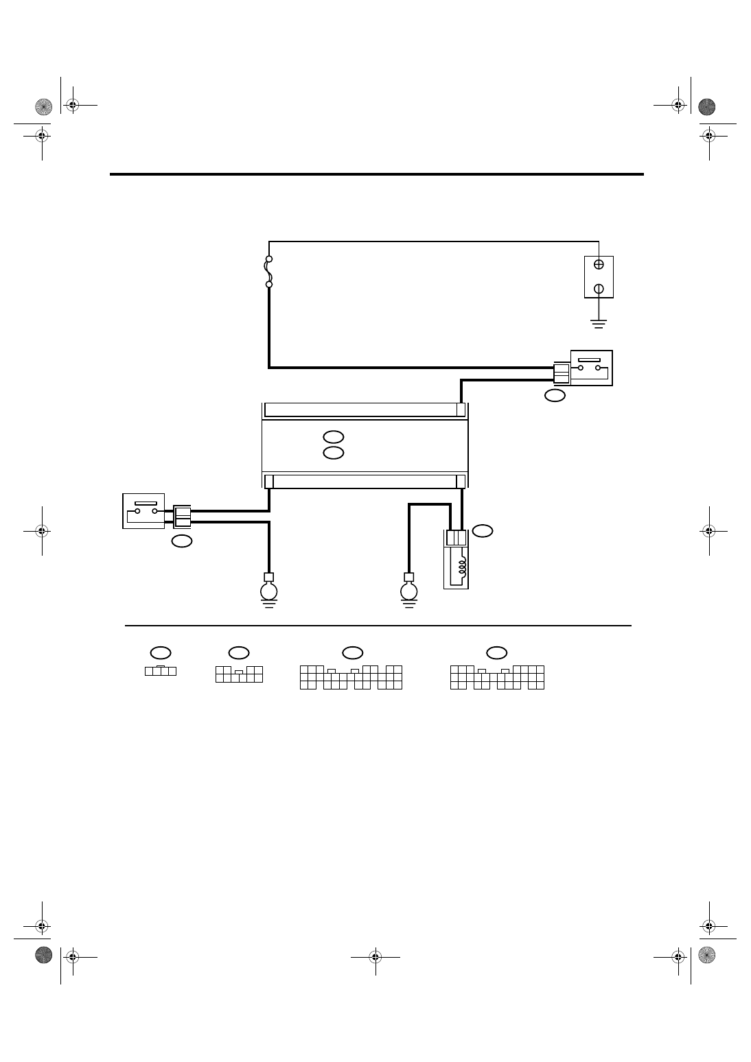
5. KEY INTERLOCK DOES NOT LOCK OR RELEASE
CS-00277
No.14
E
E
B281
C:
B280
B:
C7
B5
1
2
C13
B116
1
2
B350
B350
3
4
1 2 3 4
B350
B116
1 2
3 4
5 6 7 8 9 10
5 6 7
8
2
1
9
4
3
10
24
22 23
25
11 12 13 14 15
26
27 28
16 17 18 19
20 21
B281
5
4
6 7
8
2
1
9
3
10
22
23
11 12 13 14 15
24 25
26 27
16 17 18
28 29
19 20
21
30
B280
C:
B:
BATTERY
BODY INTEGRATED MODULE
KEY WARNING SWITCH
KEY LOCK SOLENOID
"P" RANGE SWITCH

CS-20
CONTROL SYSTEMS
AT Shift Lock Control System
Step
Check
Yes
No
1
CHECK INPUT SIGNAL OF BODY INTE-
GRATED MODULE USING SUBARU SE-
LECT MONITOR.
1) Turn the ignition switch to OFF.
2) Connect the Subaru Select Monitor to data
link connector.
3) Turn the ignition switch and Subaru Select
Monitor power switch to ON.
4) Depress the brake pedal.
5) Read the input signal of key warning switch
from Subaru Select Monitor.
<Ref. to LAN(diag)-14, OPERATION, Subaru
Select Monitor.>
Is “ON” displayed?
2
CHECK INPUT SIGNAL OF BODY INTE-
GRATED MODULE USING SUBARU SE-
LECT MONITOR.
1) Shift the select lever to “P” range.
2) Read the input signal of “P” range switch
from Subaru Select Monitor.
<Ref. to LAN(diag)-14, OPERATION, Subaru
Select Monitor.>
Is “ON” displayed?
3
CHECK DTC OF BODY INTEGRATED MOD-
ULE.
Check DTC of body integrated module.
<Ref. to LAN(diag)-24, OPERATION, Read
Diagnostic Trouble Code (DTC).>
Is DTC (B0105) displayed?
Repair or replace it
according to the
DTC.
Check the body
integrated module.
4
CHECK HARNESS BETWEEN BATTERY
AND KEY WARNING SWITCH.
1) Disconnect the connector of key warning
switch.
2) Measure the voltage of harness between
key warning switch and chassis ground.
Connector & terminal
(B350) No. 3 (+) — Chassis ground (
−
):
Is the voltage 9 — 16 V?
Repair open or
short circuit of the
harness between
battery and key
warning switch.
5
CHECK KEY WARNING SWITCH.
Measure the resistance between connector
terminals of key warning switch.
Terminal
No. 3 — No. 4:
Is the resistance more than 1
M
Ω?
Replace the key
warning switch.
6
CHECK KEY WARNING SWITCH.
1) Remove the key.
2) Measure the resistance between connector
terminals of key warning switch.
Terminal
No. 3 — No. 4:
Is the resistance more than 1
M
Ω?
Replace the key
warning switch.
7
CHECK HARNESS BETWEEN BODY INTE-
GRATED MODULE AND KEY WARNING
SWITCH.
1) Connect the connector of key warning
switch and insert the key.
2) Disconnect the connector of body inte-
grated module.
3) Measure the voltage between body inte-
grated module and chassis ground.
Connector & terminal
(B281) No. 7 (+) — Chassis ground (
−
):
Is the voltage more than 9 V?
Repair open circuit
of the harness
between body inte-
grated module and
key warning
switch.
Нет комментариевНе стесняйтесь поделиться с нами вашим ценным мнением.
Текст