Subaru Legacy (2005 year). Service manual — part 1025
IM(diag)-5
IMMOBILIZER (DIAGNOSTICS)
General Description
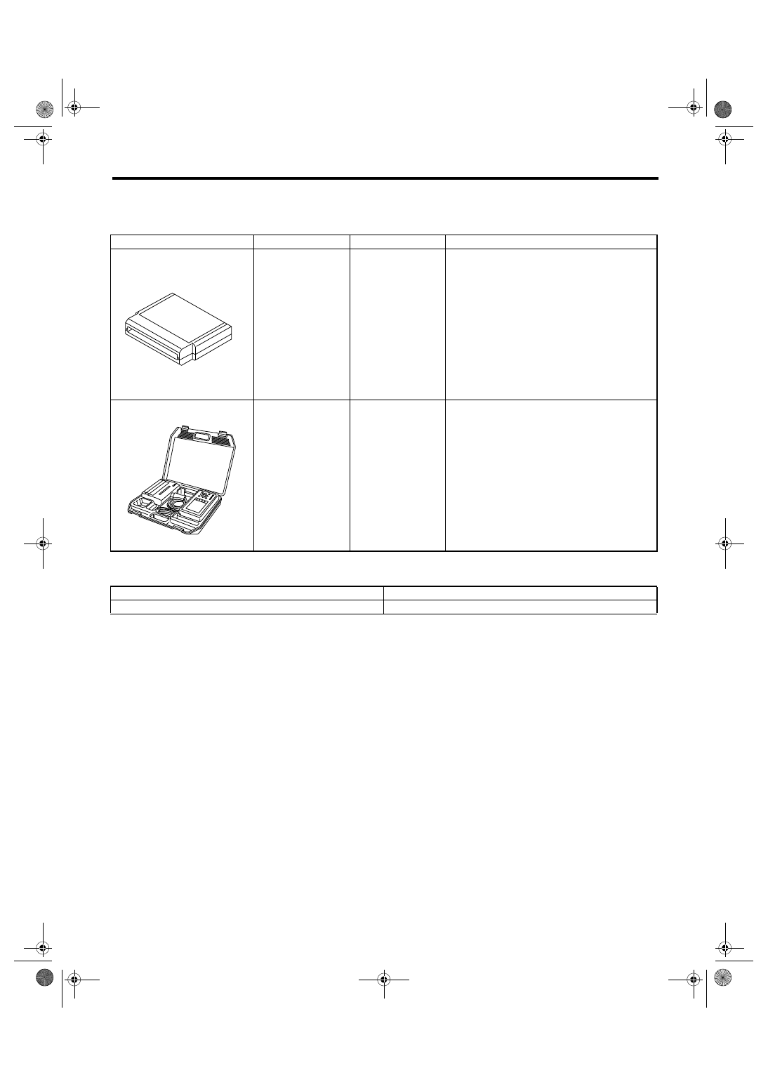
B: PREPARATION TOOL
1. SPECIAL TOOL
2. GENERAL TOOL
ILLUSTRATION
TOOL NUMBER
DESCRIPTION
REMARKS
18482AA000
(Newly adopted tool)
CARTRIDGE
Troubleshooting for electrical system.
22771AA030
SUBARU SELECT
MONITOR KIT
Troubleshooting for electrical system.
• English: 22771AA030 (Without printer)
• German: 22771AA070 (Without printer)
• French: 22771AA080 (Without printer)
• Spanish: 22771AA090 (Without printer)
TOOL NAME
REMARKS
Circuit tester
Used for measuring resistance, voltage and current.
ST18482AA000
ST22771AA030
IM(diag)-6
IMMOBILIZER (DIAGNOSTICS)
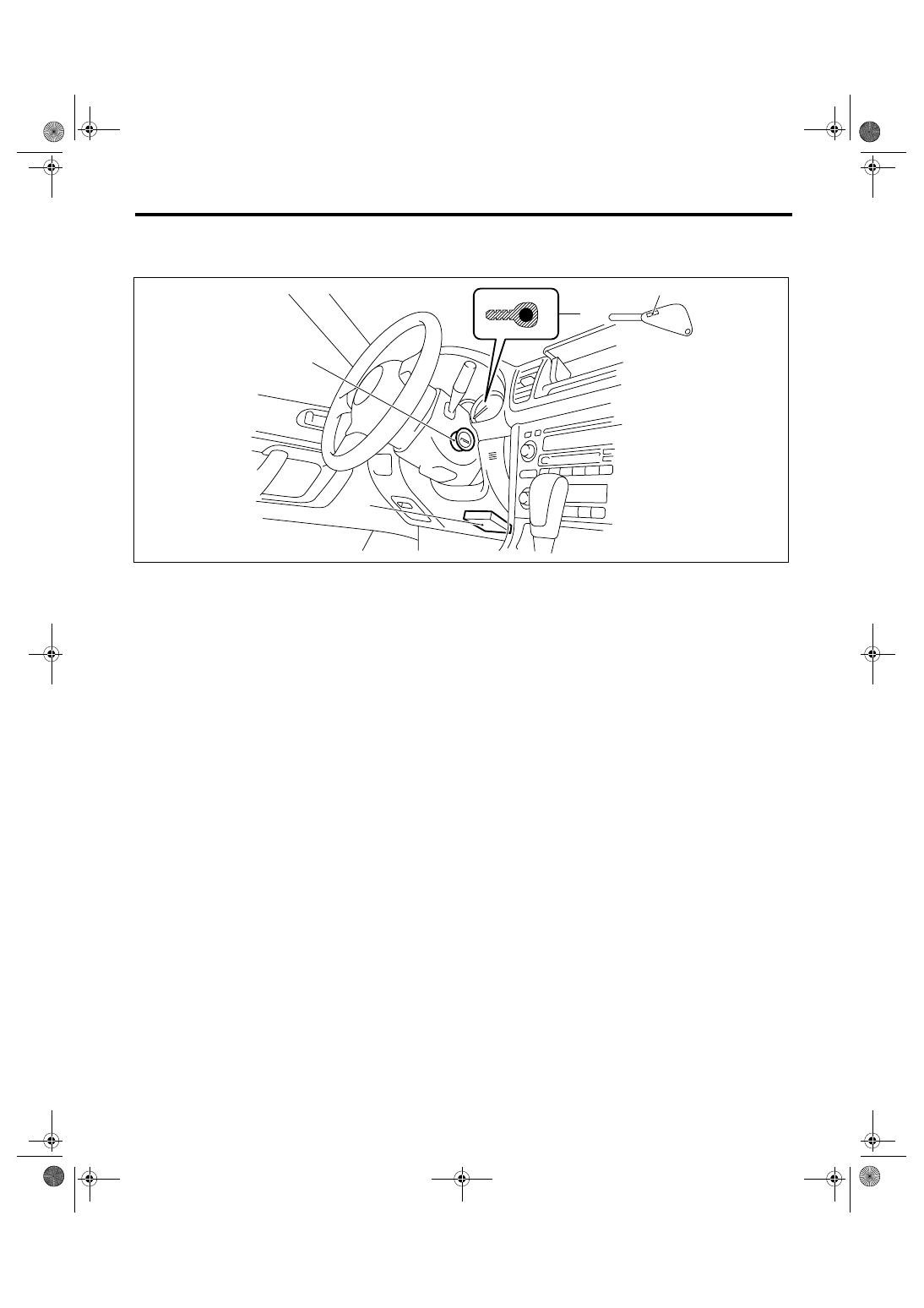
Electrical Component Location
3. Electrical Component Location
A: LOCATION
NOTE:
Body integrated module location for RHD model is symmetrically opposite.
(1)
Antenna
(3)
Body integrated module
(4)
Transponder
(2)
Immobilizer indicator light (LED
bulb)
IM-00083
(2)
(4)
(1)
(3)
IM(diag)-7
IMMOBILIZER (DIAGNOSTICS)
Immobilizer Control Module I/O Signal
4. Immobilizer Control Module
I/O Signal
A: WIRING DIAGRAM
1. IMMOBILIZER
IM(diag)-8
IMMOBILIZER (DIAGNOSTICS)
Subaru Select Monitor
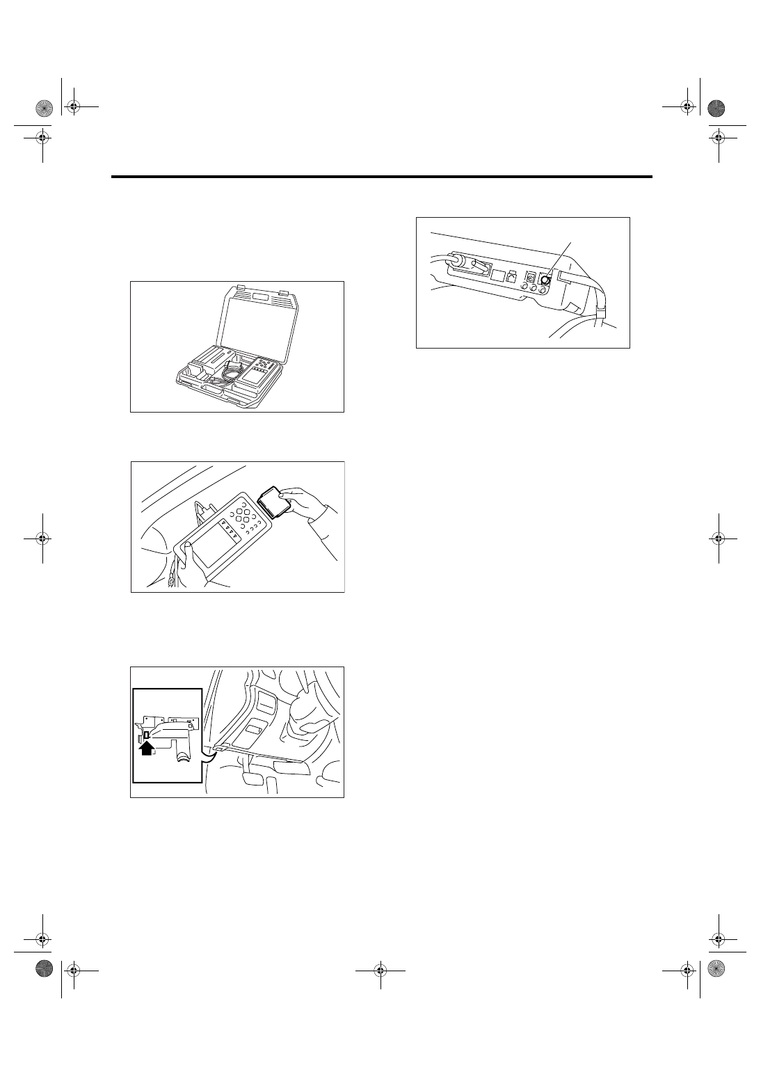
5. Subaru Select Monitor
A: OPERATION
1. HOW TO USE SUBARU SELECT MONI-
TOR
1) Prepare the Subaru Select Monitor kit.
2) Connect the diagnosis cable to Subaru Select
Monitor.
3) Insert the cartridge to Subaru Select Monitor.
4) Connect the Subaru Select Monitor to data link
connector.
(1) Data link connector is located in the lower
portion of the instrument panel (on the driver's
side).
(2) Connect the diagnosis cable to data link
connector.
CAUTION:
Do not connect the scan tools except Subaru
Select Monitor.
5) Turn the ignition switch to ON (engine OFF), and
the Subaru Select Monitor power switch to ON.
6) Using the Subaru Select Monitor, call up DTC
and various data, then record them.
2. READ DIAGNOSTIC TROUBLE CODE
(DTC) FOR ENGINE AND BODY INTEGRAT-
ED MODULE
Refer to Read Diagnostic Trouble Code for infor-
mation about how to indicate DTC. <Ref. to IM(di-
ag)-9, Read Diagnostic Trouble Code (DTC).>
3. COMMUNICATION LINE CHECK
NOTE:
The communication line between ECM and body
integrated module can be checked in “System Op-
eration Check Mode”. This is referred to as “Com-
munication line check”.
1) Connect the Subaru Select Monitor.
2) On the “System operation check mode” display,
select the {security system}.
3) Start the communication line check.
4) Is “Communication Line not Shorted” displayed
on screen?
If displayed, go to step 5).
If “NO”, go to step 6).
5) After diagnostic results, it is determined that the
circuit is not shorted. Finish the communication line
check.
6) If a problem is detected, repair the trouble
cause. <Ref. to IM(diag)-21, DTC P1572 IMM CIR-
CUIT FAILURE (EXCEPT ANTENNA CIRCUIT),
Diagnostic Procedure with Diagnostic Trouble
Code (DTC).>
CC-00028
EN-00039
IM-00084
(1) Power switch
CC-00045
(1)
Нет комментариевНе стесняйтесь поделиться с нами вашим ценным мнением.
Текст