Subaru Legacy (2005 year). Service manual — part 1026
IM(diag)-9
IMMOBILIZER (DIAGNOSTICS)
Read Diagnostic Trouble Code (DTC)
6. Read Diagnostic Trouble
Code (DTC)
A: OPERATION
1. ENGINE ECM
1) On the “Main Menu” display screen, select the
{Each System Check} and press the [YES] key.
2) On the “System Selection Menu” display screen,
select the {Engine Control System} and press the
[YES] key.
3) Press the [YES] key after the information of en-
gine type is displayed.
4) On the “Engine Diagnosis” display screen, select
the {Diagnostic Code(s) Display}, and then press
the [YES] key.
5) On the “Diagnostic Code(s) Display” display
screen, select the {Current Diagnostic Code(s)} or
{History Diagnostic Code(s)}, and then press the
[YES] key.
NOTE:
• For detailed operation procedure, refer to the
SUBARU SELECT MONITOR OPERATION MAN-
UAL.
• For detailed concerning DTC, refer to the List of
DTC. <Ref. to IM(diag)-15, LIST, List of Diagnostic
Trouble Code (DTC).>
2. BODY INTEGRATED MODULE
1) On the “Main Menu” display screen, select the
{Each System Check} and press the [YES] key.
2) On the “System Selection Menu” display screen,
select the {Integ. unit mode} and press the [YES]
key.
3) Press the [YES] key after the {Integ. unit mode}
is displayed.
4) On the “Integ. unit mode failure diag” display
screen, select the {Diagnostic Code(s) Display}
and press the [YES] key.
NOTE:
• For detailed operation procedure, refer to the
SUBARU SELECT MONITOR OPERATION MAN-
UAL.
• For detailed concerning DTC, refer to the List of
DTC. <Ref. to IM(diag)-15, LIST, List of Diagnostic
Trouble Code (DTC).>
IM(diag)-10
IMMOBILIZER (DIAGNOSTICS)
Clear Memory Mode
7. Clear Memory Mode
A: OPERATION
1. ENGINE ECM
1) On the “Main Menu” display screen, select the
{Each System Check} and press the [YES] key.
2) On the “System Selection Menu” display screen,
select the {Engine Control System} and press the
[YES] key.
3) Press the [YES] key after the information of en-
gine type is displayed.
4) On the “Engine Diagnosis” display screen, select
the {Clear Memory} and press the [YES] key.
5) When the “Done” are shown on the display
screen, turn the Subaru Select Monitor and ignition
switch to OFF.
NOTE:
• After the memory has been cleared, the idle air
control solenoid valve must be initialized. To exe-
cute this procedure, turn the ignition switch to ON.
Wait for 3 seconds before starting the engine.
• For detailed operation procedure, refer to the
SUBARU SELECT MONITOR OPERATION MAN-
UAL.
2. BODY INTEGRATED MODULE
1) On the “Main Menu” display screen, select the
{Each System Check} and press the [YES] key.
2) On the “System Selection Menu” display screen,
select the {Integ. unit mode} and press the [YES]
key.
3) Press the [YES] key after the {Integ. unit mode}
is displayed.
4) On the “Integ. unit mode failure diag” display
screen, select the {Clear Memory} and press the
[YES] key.
5) When the “Done” are shown on the display
screen, turn the Subaru Select Monitor and ignition
switch to OFF.
NOTE:
For detailed operation procedure, refer to the SUB-
ARU SELECT MONITOR OPERATION MANUAL.
IM(diag)-11
IMMOBILIZER (DIAGNOSTICS)
Diagnostics Chart for Immobilizer Indicator Light
8. Diagnostics Chart for Immobilizer Indicator Light
A: INSPECTION
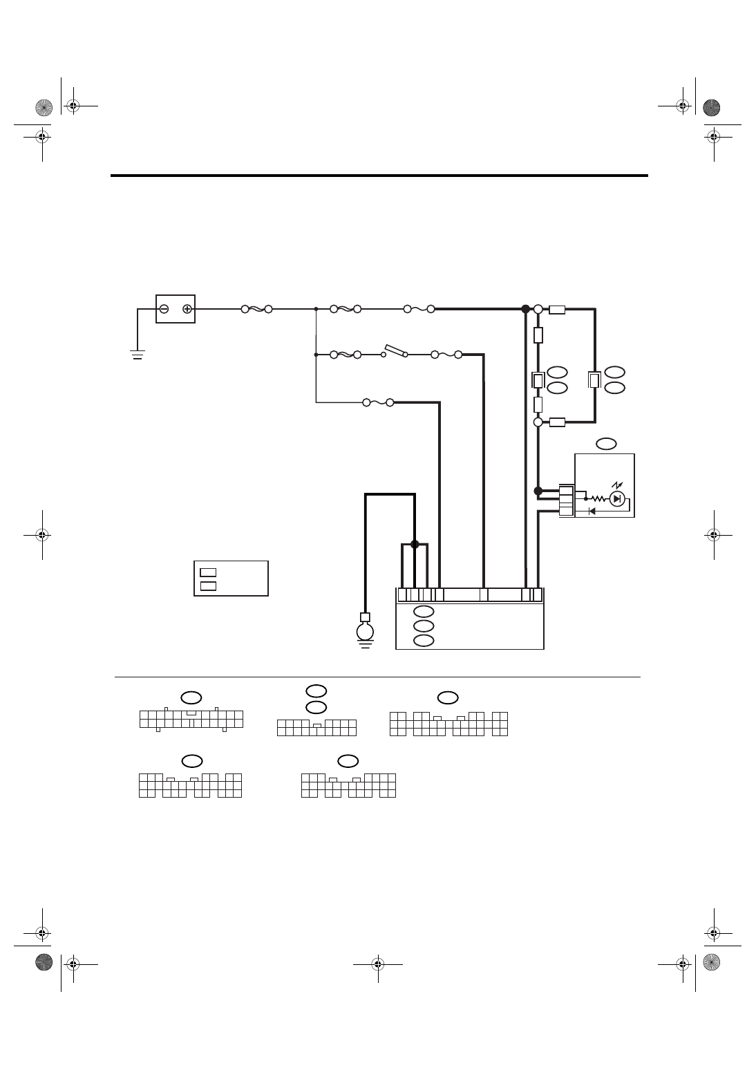
1. CHECK IMMOBILIZER INDICATOR CIRCUIT
WIRING DIAGRAM:
IM-00138
MAIN SBF
SBF-3
BATTERY
COMBINATION METER
BODY INTEGRATED MODULE
i10
R98
i53
F/B No.7
F/B No.12
IGNITION
SWITCH
A33
C2
B7
C9
C8
A17
A2
E
A:
A1
13
A1
M/B No.8
SBF-8
B22
i84
A:
B280
B:
B281
C:
5 6 7
8
2
1
9
4
3
10
24
22 23
25
11 12 13 14 15
26
27 28
16 17 18 19
20 21
B281
i84
1 2
3 4
5 6
7 8
9 10 11 12 13 14 15 16 17 18 19 20 21 22 23
24 25
26 27 28 29
30 31 32 33
34 35
5
4
6 7
8
2
1
9
3
10
22
23
11 12 13 14 15
24 25
26 27
16 17 18
28 29
19 20
21
30
B280
i10
2
1
3 4
6 7 8 9 10
22
21
20
19
18
17
16
15
14
13
12
11
5
1 2 3
8
9 10
4
11 12 13 14 15 16
5 6 7
17 18
i53
A:
C:
B:
A:
RHD
LHD
11
R167
i102
: LHD MODEL
: RHD MODEL
LHD
RHD
i102
LHD
RHD
IMMOBILIZER
INDICATOR
LIGHT
IM(diag)-12
IMMOBILIZER (DIAGNOSTICS)
Diagnostics Chart for Immobilizer Indicator Light
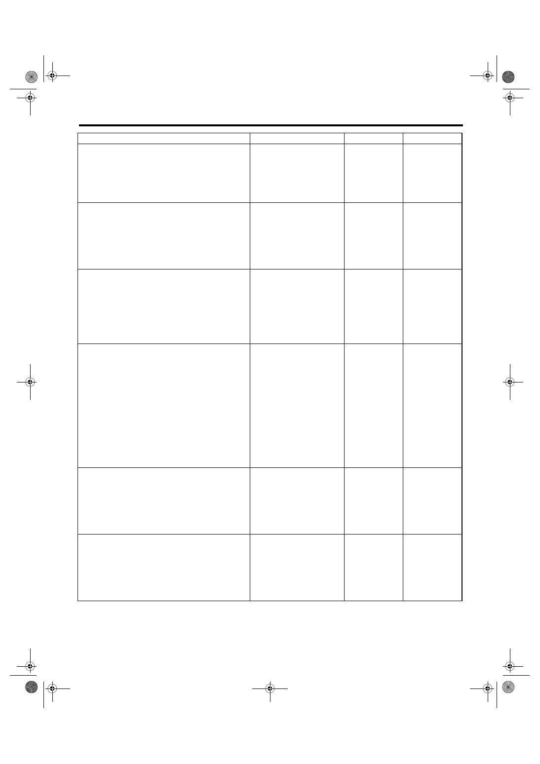
Step
Check
Yes
No
1
CHECK IMMOBILIZER INDICATOR LIGHT.
1) Turn the ignition switch to OFF.
2) Disconnect the harness connector from
body integrated module.
3) Connect the resistor (100
Ω) between body
integrated module harness connector terminal
(i84) No. 33 and chassis ground.
Does the immobilizer indicator
light illuminate?
2
CHECK BODY INTEGRATED MODULE
GROUND CIRCUIT.
Measure the resistance between body inte-
grated module harness connector terminal and
chassis ground.
Connector & terminal
(B280) No. 22 — Chassis ground:
(B281) No. 8, No. 9 — Chassis ground:
Is the resistance less than 10
Ω?
Repair the open
circuit of body inte-
grated module
ground circuit.
3
CHECK BODY INTEGRATED MODULE IGNI-
TION CIRCUIT.
1) Turn the ignition switch to ON. (engine
OFF)
2) Measure the voltage between body inte-
grated module harness connector terminal and
chassis ground.
Connector & terminal
(i84) No. 1 (+) — Chassis ground (
−
):
Is the voltage more than 10 V? Go to step 4.
Check the harness
for open or short
circuit between
body integrated
module and igni-
tion switch.
4
CHECK BODY INTEGRATED MODULE
POWER SUPPLY CIRCUIT.
1) Turn the ignition switch to OFF.
2) Measure the voltage between body inte-
grated module harness connector terminal and
chassis ground.
Connector & terminal
(B280) No. 7 (+) — Chassis ground (
−
):
(B281) No. 2 (+) — Chassis ground (
−
):
Is the voltage more than 10 V? Replace the body
integrated module
<Ref. to SL-44,
Body Integrated
Module.> and
replace all the igni-
tion keys (includ-
ing transponder).
Execute the regis-
tration procedure
next. Refer to
“IMMOBILIZER
TEACHING
OPERATION
MANUAL”.
Check the harness
for open or short
circuit between
body integrated
module and fuse.
5
CHECK COMBINATION METER CIRCUIT.
1) Remove the combination meter. <Ref. to
IDI-15, Combination Meter.>
2) Measure the voltage between the combina-
tion meter harness connector terminal and
chassis ground.
Connector & terminal
(i10) No. 1, No. 2 (+) — Chassis ground (
−
):
Is the voltage more than 10 V? Go to step 6.
Check the harness
for open or short
circuit between
combination meter
and fuse.
6
CHECK COMBINATION METER CIRCUIT.
Measure the resistance between body inte-
grated module harness connector terminal and
combination meter harness connector termi-
nal.
Connector & terminal
(i84) No. 33 — (i10) No. 17:
Is the resistance less than 10
Ω?
LED bulb malfunc-
tion. Replace the
combination meter
case assembly.
<Ref. to IDI-16,
DISASSEMBLY,
Combination
Meter.>
Repair the har-
ness or connector.
Нет комментариевНе стесняйтесь поделиться с нами вашим ценным мнением.
Текст