Subaru Legacy (2005 year). Service manual — part 303
LU(H4DOTC)-11
LUBRICATION
Oil Pump
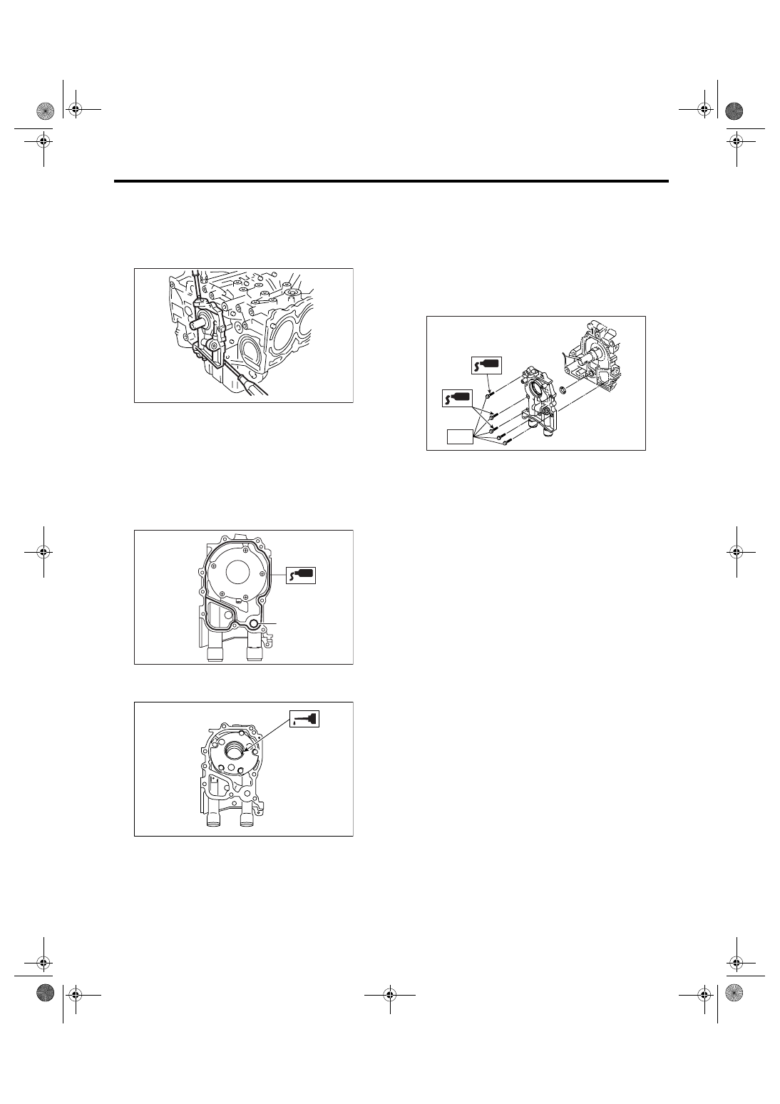
14) Remove the oil pump by using flat tip screw-
driver.
CAUTION:
Be careful not to scratch mating surfaces of
cylinder block and oil pump.
B: INSTALLATION
Install in the reverse order of removal.
Perform the following.
1) Apply liquid gasket to the mating surfaces of oil
pump.
Liquid gasket:
THREE BOND 1215 (Part No. 004403007) or
equivalent
2) Replace the O-ring (A) with a new one.
3) Apply a coat of engine oil to the inside of oil seal.
4) Position the oil pump, aligning the notched area
with the crankshaft, and push the oil pump straight.
CAUTION:
• Make sure the oil seal lip is not folded.
• Be careful not to scratch the oil seal when in-
stalling oil pump on cylinder block.
5) Install the oil pump.
6) Apply liquid gasket to the three bolts thread. (if to
be reused)
Liquid gasket:
THREE BOND 1215 (Part No. 004403007) or
equivalent
Tightening torque:
6.4 N
⋅
m (0.65 kgf-m, 4.7 ft-lb)
LU-00016
LU-00017
( A )
ME-00312
LU-02103
T
LU(H4DOTC)-12
LUBRICATION
Oil Pump
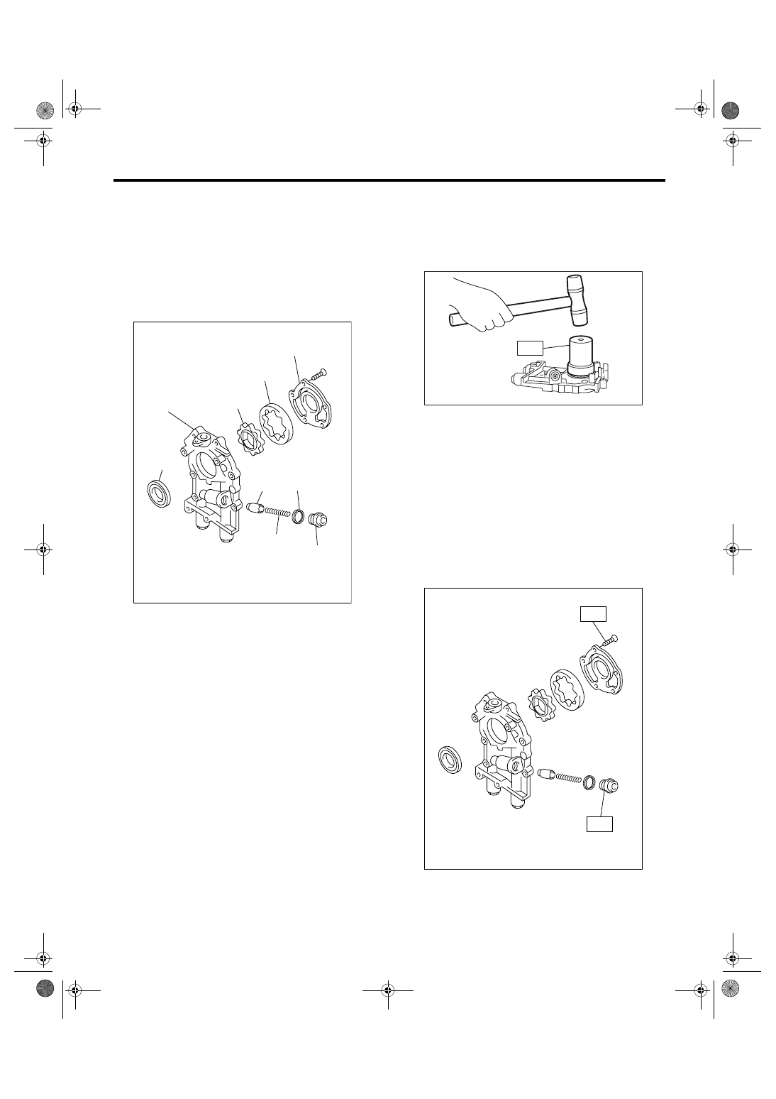
C: DISASSEMBLY
Remove the screw which secures oil pump cover
and then disassemble oil pump. Inscribe alignment
marks on the inner and outer rotors so that they can
be replaced in their original positions during reas-
sembly.
CAUTION:
Before disassembling the oil pump, remove the
relief valve.
D: ASSEMBLY
1) Install the front oil seal using ST.
ST
499587100
OIL SEAL INSTALLER
NOTE:
Use a new oil seal.
2) Apply a coat of engine oil to inner and outer ro-
tors.
3) Install the inner and outer rotors in their original
positions.
4) Install the oil relief valve and install relief valve
spring and plug.
NOTE:
Use a new gasket.
5) Install the oil pump cover.
Tightening torque:
T1: 5.4 N
⋅
m (0.55 kgf-m, 4.0 ft-lb)
T2: 44 N
⋅
m (4.5 kgf-m, 33 ft-lb)
(A) Oil seal
(B) Pump case
(C) Inner rotor
(D) Outer rotor
(E) Pump cover
(F) Relief valve
(G) Relief valve spring
(H) Plug
(I) Gasket
LU-00020
(E)
(D)
(C)
(B)
(A)
(F)
(G)
(I)
(H)
LU-00021
ST
LU-00022
T1
T2
LU(H4DOTC)-13
LUBRICATION
Oil Pump
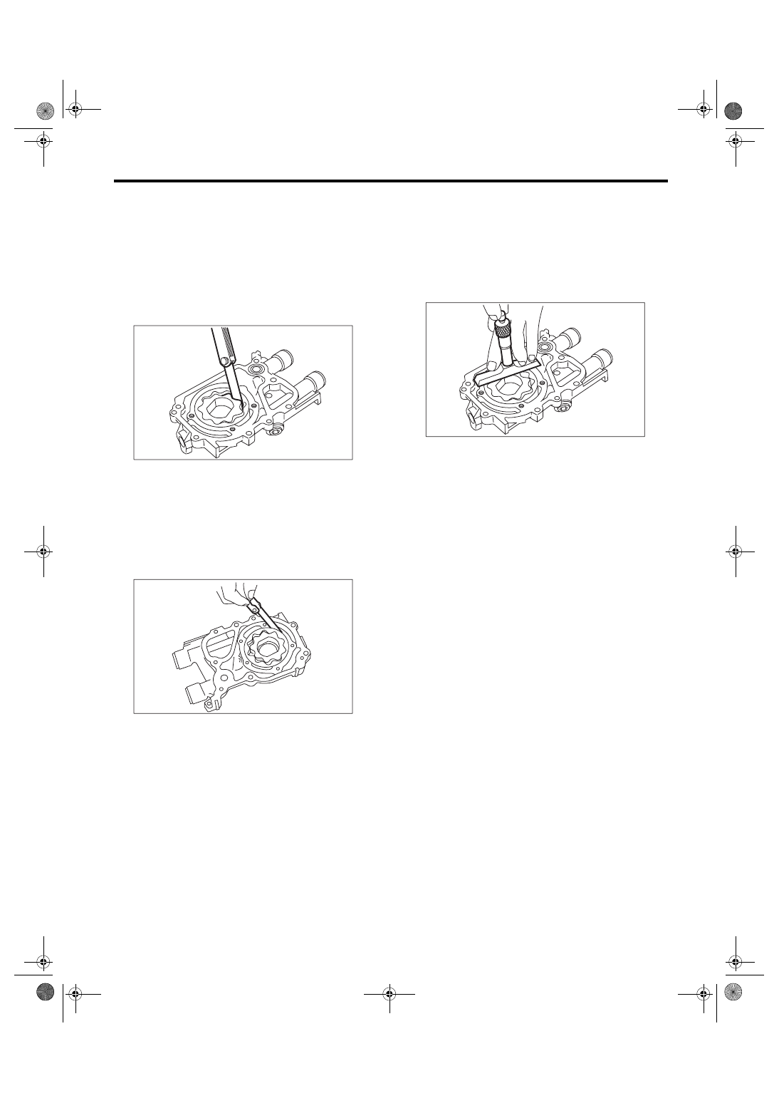
E: INSPECTION
1. TIP CLEARANCE
Measure the tip clearance of rotors. If the clearance
is out of the specification, replace rotors as a
matched set.
Tip clearance:
Specification
0.04 — 0.14 mm (0.0016 — 0.0055 in)
2. CASE CLEARANCE
Measure the clearance between outer rotor and oil
pump rotor housing. If the clearance is out of the
specification, replace the oil pump case.
Case clearance:
Specification
0.10 — 0.175 mm (0.0039 — 0.0069 in)
3. SIDE CLEARANCE
Measure the clearance between oil pump inner ro-
tor and pump cover. If the clearance exceeds the
specification, replace the rotor or pump body.
Side clearance:
Specification
0.02 — 0.07 mm (0.0008 — 0.0028 in)
4. OIL RELIEF VALVE
Check the valve for fitting condition and damage,
and the relief valve spring for damage and deterio-
ration. Replace the parts if defective.
Relief valve spring:
Free length
73.7 mm (2.902 in)
Installed length
54.7 mm (2.154 in)
Load when installed
93.1 N (9.49 kgf, 20.88 lbf)
5. OIL PUMP CASE
Check the oil pump case for worn shaft hole,
clogged oil passage, worn rotor chamber, cracks
and other faults.
6. OIL SEAL
Check the oil seal lips for deformation, hardening,
wear, etc., and replace if defective.
LU-00023
LU-00024
LU-00025
LU(H4DOTC)-14
LUBRICATION
Oil Pan and Strainer
5. Oil Pan and Strainer
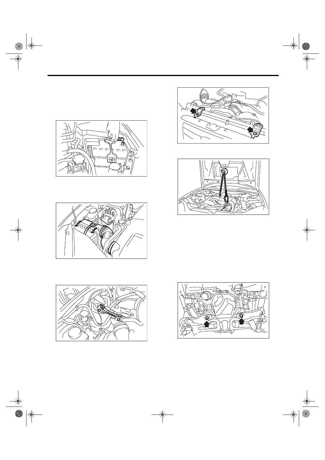
A: REMOVAL
1) Set the vehicle on a lift.
2) Remove the front wheels.
3) Remove the collector cover.
4) Disconnect the ground cable from battery.
5) Disconnect the connector from mass airflow
sensor.
6) Remove the air intake boot and air cleaner upper
cover.
7) Remove the intercooler.
<Ref. to IN(H4DOTC)-12, REMOVAL, Intercool-
er.>
8) Remove the pitching stopper.
9) Remove the linear motion mounting.
<Ref. to ME(H4DOTC)-38, REMOVAL, Linear Mo-
tion Mounting.>
10) Remove the radiator upper brackets.
11) Support the engine with a lifting device and
wire ropes.
12) Lift-up the vehicle.
CAUTION:
When lifting up the vehicle, raise up wire ropes
at the same time.
13) Remove the under cover.
14) Drain the engine oil.
15) Remove the front exhaust pipe.
<Ref. to EX(H4DOTC)-5, REMOVAL, Front Ex-
haust Pipe.>
16) Remove the nuts which install front cushion
rubber onto front crossmember.
17) Remove the bolts which install oil pan on cylin-
der block with the engine raised up.
18) Insert the oil pan cutter blade into the gap be-
tween cylinder block and oil pan.
CAUTION:
Do not use a screwdriver or similar tool in place
of oil pan cutter.
19) Remove the oil strainer.
IN-00203
LU-00220
LU-00221
CO-00040
LU-00222
LU-02023
Нет комментариевНе стесняйтесь поделиться с нами вашим ценным мнением.
Текст