Subaru Legacy IV (2008 year). Service manual — part 741
5AT-88
Drive Pinion Shaft Assembly
AUTOMATIC TRANSMISSION
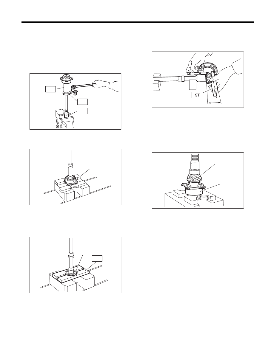
C: DISASSEMBLY
1) Flatten the lock nut tab, and then remove the
lock nut while holding the rear spline part of the
shaft using ST1 and ST2. Pull out the drive pinion
collar.
ST1
18667AA010
HOLDER
ST2
499787700
WRENCH
ST3
499787500
ADAPTER
2) Remove the O-ring.
3) Separate the roller bearing and outer race from
shaft using a press.
4) Separate the front roller bearing from the shaft
using a press and the ST.
ST
498517000
REPLACER
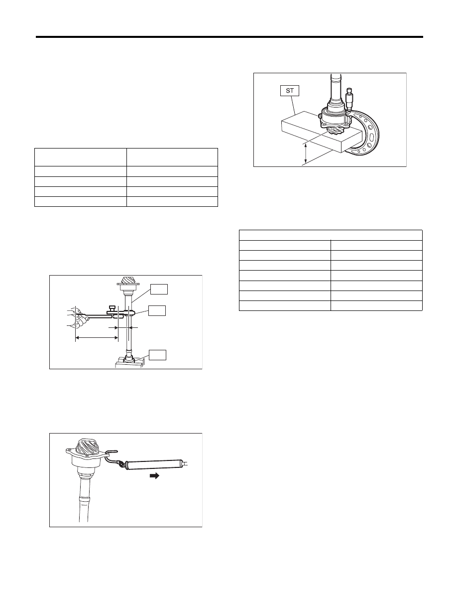
D: ASSEMBLY
1) Measure the dimension “A” of the drive pinion
shaft.
ST
398643600
GAUGE
2) Using a press, press-fit the new roller bearing
into the specified position.
NOTE:
If excessive force is applied to roller bearing, the
roller bearing will not turn easily.
3) After fitting a new O-ring to the shaft, attach the
drive pinion collar to the shaft.
(A) Outer race
(A) Front roller bearing
AT-00197
ST1
ST3
ST2
AT-00198
(A)
AT-00199
(A)
ST
A Measured value
(A) Drive pinion shaft
(B) Roller bearing
A
AT-00200
AT-00201
(B)
(A)
5AT-89
Drive Pinion Shaft Assembly
AUTOMATIC TRANSMISSION
4) Tighten the new lock nuts using ST1, ST2 and
ST3.
Use the calculation below to calculate the tighten-
ing torque.
T2 = L2/(L1 + L2) × T1
T1: 116 N·m (11.8 kgf-m, 85.6 ft-lb)
[Required torque setting]
T2: Tightening torque
L1: ST2 length 0.072 m (2.83 in)
L2: Torque wrench length
Example:
ST1
18667AA010
HOLDER
ST2
499787700
WRENCH
ST3
499787500
ADAPTER
NOTE:
Attach ST2 to torque wrench as straight as possi-
ble.
5) Measure the starting torque of the bearing. Make
sure the starting torque is within the specified
range. If the torque is not within specified range, re-
place the roller bearing.
Starting torque:
7.6 — 38.1 N (0.775 — 3.88 kgf, 1.7 — 8.6 lb)
6) Crimp the locknut in 2 locations.
7) Measure the dimension “B” of the drive pinion
shaft.
ST
398643600
GAUGE
8) Calculate the thickness “t” mm (in) of the drive
pinion shim.
t = 6.5
r0.0625 (0.2559r0.0025) – (B – A)
9) Select three or less shims from following table.
E: INSPECTION
• Make sure that all component parts are free of
scratches, holes and other faults.
• Adjust the tooth alignment. <Ref. to 5AT-90, AD-
JUSTMENT, Drive Pinion Shaft Assembly.>
Torque wrench length
m (in)
Tightening torque
N·m (kgf-m, ft-lb)
0.4 (15.75)
98 (10.0, 72.3)
0.45 (17.72)
100 (10.2, 73.8)
0.5 (19.69)
101 (10.3, 74.5)
0.55 (21.65)
102 (10.4, 75.2)
ST1
AT-00202
L1 [m (in)]
L2 [m (in)]
ST2
ST3
AT-00203
B Measured value
Drive pinion shim
Part No.
Thickness mm (in)
31451AA180
0.150 (0.0059)
31451AA190
0.175 (0.0069)
31451AA200
0.200 (0.0079)
31451AA210
0.225 (0.0089)
31451AA220
0.250 (0.0098)
31451AA230
0.275 (0.0108)
B
AT-00204
5AT-90
Drive Pinion Shaft Assembly
AUTOMATIC TRANSMISSION
F: ADJUSTMENT
1) Remove the liquid gasket from the mating sur-
face completely.
2) Install the converter case to oil pump cover, and
secure them with tightening four bolts evenly.
NOTE:
Use an old gasket or aluminum washer to prevent
damaging the mating surface of the housing.
Tightening torque:
41 N·m (4.2 kgf-m, 30.2 ft-lb)
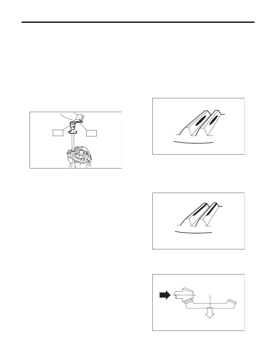
3) Rotate the drive pinion a few times using ST1
and ST2.
ST1
18667AA010
HOLDER
ST2
499787700
WRENCH
4) Adjust the drive pinion and hypoid driven gear
backlash. <Ref. to 5AT-96, ADJUSTMENT, Front
Differential Assembly.>
5) Apply lead-free red dye evenly on the surface of
three to four teeth of the hypoid driven gear. Rotate
the drive pinion in the leftward and rightward for
several times. Remove the oil pump cover, and
check the tooth contact pattern.
If the teeth contact is inappropriate, adjust the
backlash or thickness of the shim. <Ref. to 5AT-96,
ADJUSTMENT, Front Differential Assembly.>
• Correct tooth contact
Check item: Tooth contact surface is slightly
shifted toward the toe side under a no-load con-
dition. (When driving, it moves towards the heel
side.)
• Face contact
Check item: Backlash is too large.
Contact pattern
Corrective action: Increase the thickness of pinion
height adjusting washer according to the proce-
dures for moving the drive pinion closer to the driv-
en gear.
AT-01985
ST2
ST1
(A) Toe side
(B) Heel side
(A)
(B)
MT-01401
AT-00208
AT-00212
5AT-91
Drive Pinion Shaft Assembly
AUTOMATIC TRANSMISSION
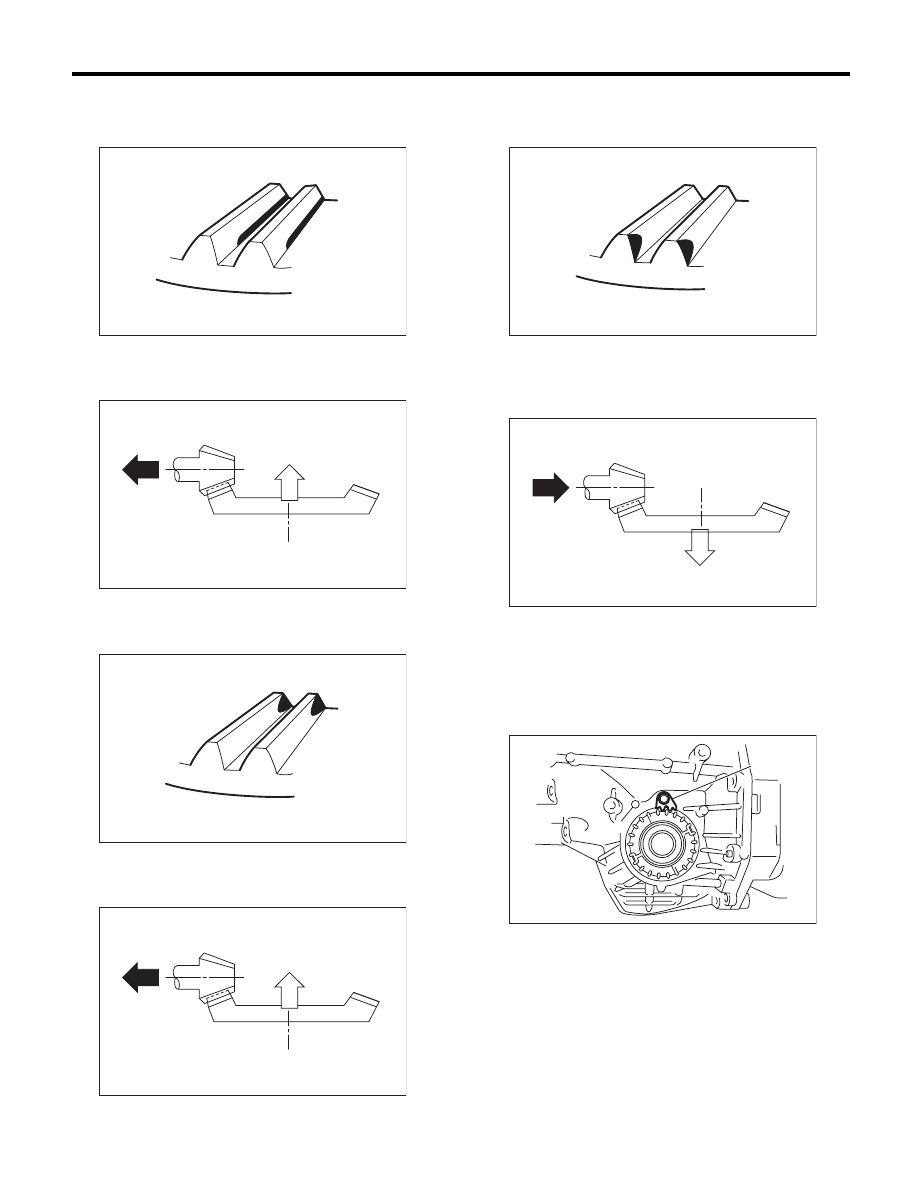
• Flank contact
Check item: Backlash is too small.
Contact pattern
Corrective action: Reduce the thickness of pinion
height adjusting washer according to the procedure
for bringing the drive pinion away from driven gear.
• Toe contact (inside contact)
Check item: Contact area is too small.
Contact pattern
Corrective action: Reduce the thickness of pinion
height adjusting washer according to the procedure
for bringing the drive pinion away from driven gear.
• Heel contact (outside end contact)
Check item: Contact area is too small.
Contact pattern
Corrective action: Increase the thickness of pinion
height adjusting washer according to the proce-
dures for moving the drive pinion closer to the driv-
en gear.
6) If tooth contact is correct, mark the retainer posi-
tion and loosen it. After fitting a new O-ring and oil
seal, screw in the retainer to the marked position.
Tighten the lock plate with specified torque.
Tightening torque:
25 N·m (2.5 kgf-m, 18.4 ft-lb)
AT-00209
AT-00213
AT-00210
AT-00213
(A) Lock plate
AT-00211
AT-00212
AT-01988
(A)
Нет комментариевНе стесняйтесь поделиться с нами вашим ценным мнением.
Текст