Subaru Legacy IV (2008 year). Service manual — part 742
5AT-92
Front Differential Assembly
AUTOMATIC TRANSMISSION
34.Front Differential Assembly
A: REMOVAL
1) Remove the transmission assembly from vehicle
body. <Ref. to 5AT-39, REMOVAL, Automatic
Transmission Assembly.>
2) Pull out the torque converter assembly. <Ref. to
5AT-67, REMOVAL, Torque Converter Assembly.>
3) Remove the transmission harness connector
from stay.
4) Remove the oil charge pipe. <Ref. to 5AT-66,
REMOVAL, Oil Charge Pipe.>
5) Remove the ATF inlet and outlet pipes. <Ref. to
5AT-62, REMOVAL, ATF Cooler Pipe and Hose.>
6) Separate the converter case from the transmis-
sion case. <Ref. to 5AT-81, REMOVAL, Converter
Case.>
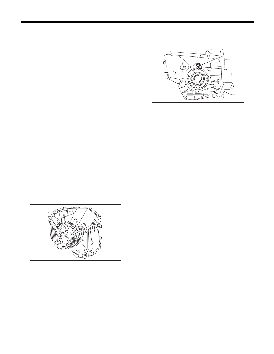
7) Remove the differential side retainers using ST.
NOTE:
Hold the differential case assembly by hand to
avoid damaging the retainer mounting hole of the
converter case.
ST
18630AA010
WRENCH COMPL RETAINER
8) Remove the differential assembly while being
careful not to damage the attachment part of retain-
er.
B: INSTALLATION
1) When installing the front differential assembly to
case, be careful not to damage the inside of case
(particularly, the differential side retainer mating
surface).
2) Install the O-ring to left and right side retainer.
3) Using the ST, install the side retainer. <Ref. to
5AT-92, INSTALLATION, Front Differential Assem-
bly.>
ST
18630AA010
WRENCH COMPL RETAINER
4) Adjust the backlash of the front differential. <Ref.
to 5AT-96, ADJUSTMENT, Front Differential As-
sembly.>
5) Install the lock plate.
Tightening torque:
25 N·m (2.5 kgf-m, 18.4 ft-lb)
6) Install the converter case to the transmission
case. <Ref. to 5AT-81, INSTALLATION, Converter
Case.>
7) Install the transmission harness connector to the
stay.
8) Install the ATF cooler pipe. <Ref. to 5AT-63, IN-
STALLATION, ATF Cooler Pipe and Hose.>
9) Install the oil charge pipe together with an O-
ring. <Ref. to 5AT-66, INSTALLATION, Oil Charge
Pipe.>
10) Install the torque converter assembly. <Ref. to
5AT-67, INSTALLATION, Torque Converter As-
sembly.>
11) Install the transmission assembly to the vehi-
cle. <Ref. to 5AT-43, INSTALLATION, Automatic
Transmission Assembly.>
(A) Front differential ASSY
AT-01987
(A)
(A) Lock plate
AT-01988
(A)
5AT-93
Front Differential Assembly
AUTOMATIC TRANSMISSION
C: DISASSEMBLY
1. DIFFERENTIAL CASE ASSEMBLY
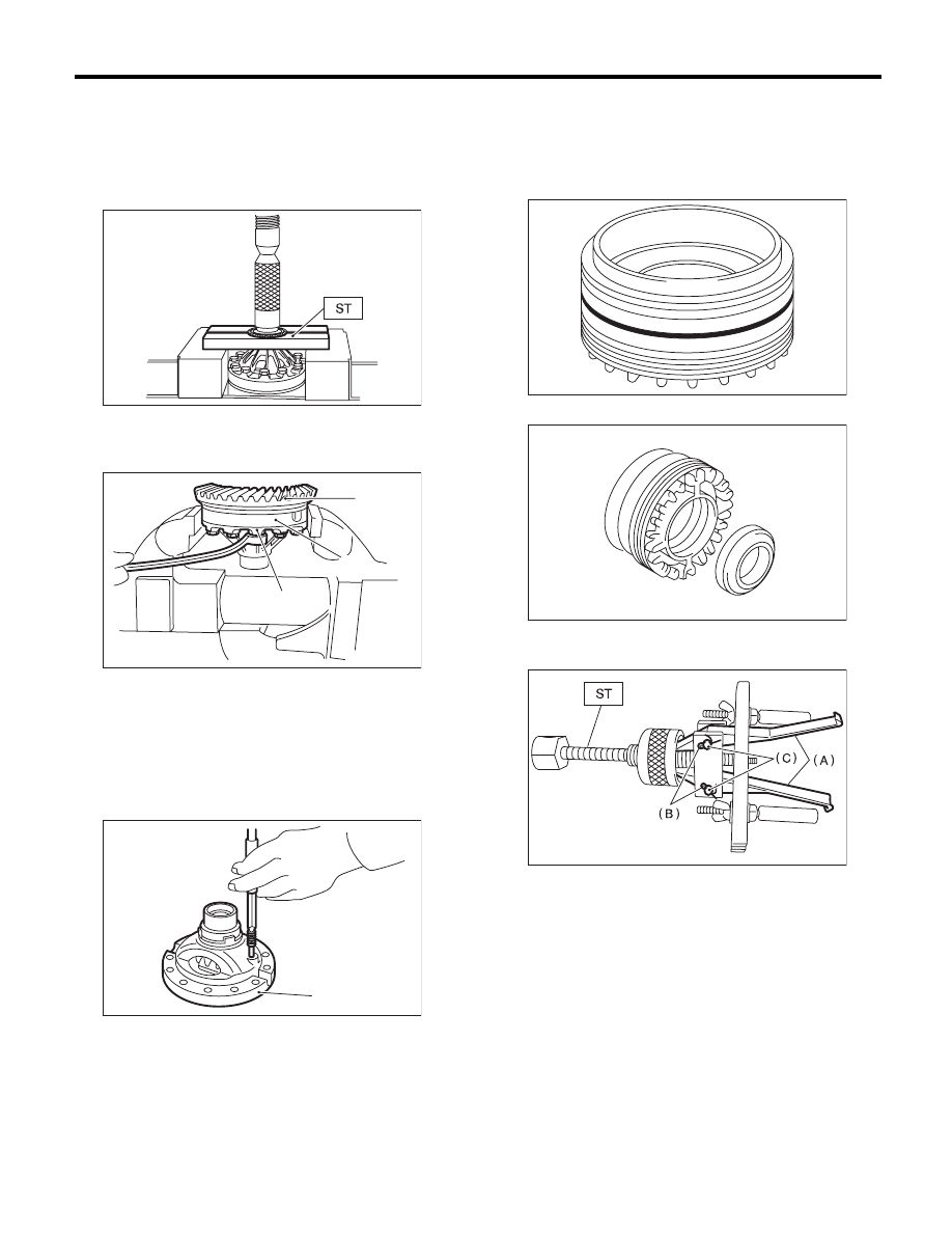
1) Remove the taper roller bearing using the ST
and the press.
ST
498077000
REMOVER
2) Secure the case in a vise, remove the hypoid
driven gear tightening bolts, and then separate the
hypoid driven gear into case (RH) and case (LH).
3) Pull out the straight pin and shaft, and then re-
move the differential bevel gear, washer and differ-
ential bevel pinion.
2. SIDE RETAINER
NOTE:
After adjusting the drive pinion backlash and tooth
contact, remove and install the oil seal and O-ring.
1) Remove the O-ring.
2) Remove the oil seal.
3) Remove the split pin, and then remove the claw.
ST
398527700
PULLER ASSY
(A) Hypoid driven gear
(B) Differential case (RH)
(C) Differential case (LH)
(A) Differential case (RH)
AT-00216
(B)
AT-00217
(A)
(C)
AT-00218
(A)
(A) Claw
(B) Split pin
(C) Pin
AT-00219
MT-01454
AT-00221
5AT-94
Front Differential Assembly
AUTOMATIC TRANSMISSION
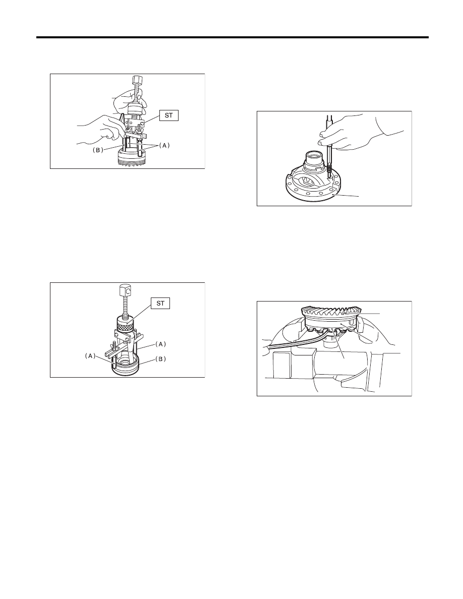
4) Attach two claws to the outer race, and set the
ST to side retainer.
ST
398527700
PULLER ASSY
5) Restore the removed claws to original position,
and install the pin and split pin.
6) Hold the shaft of ST to avoid removing from side
retainer, and then remove the bearing outer race.
ST
398527700
PULLER ASSY
NOTE:
Replace the bearing inner and outer races as a sin-
gle unit.
D: ASSEMBLY
1. DIFFERENTIAL CASE ASSEMBLY
1) Install the washer, differential bevel gear and dif-
ferential bevel pinion in the differential case (RH).
Insert the pinion shaft.
2) Attach the straight pin in the reverse direction.
3) Install the washer and differential bevel gear to
differential case (LH). Put the case on the differen-
tial case (RH), and assemble two cases.
4) Install the hypoid driven gear and secure by
tightening the bolt.
Tightening torque:
70 N·m (7.1 kgf-m, 51.6 ft-lb)
(A) Shaft
(B) Claw
(A) Shaft
(B) Side retainer
AT-00222
AT-00223
(A) Differential case (RH)
(A) Hypoid driven gear
(B) Differential case (RH)
(C) Differential case (LH)
AT-00218
(A)
(B)
AT-00217
(A)
(C)
5AT-95
Front Differential Assembly
AUTOMATIC TRANSMISSION
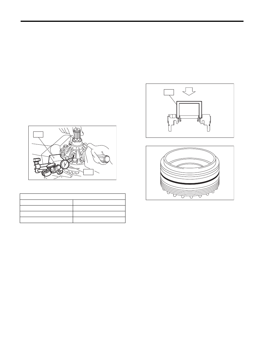
5) Measurement of backlash (Selection of washer)
(1) Install the SUBARU genuine axle shaft to
differential case.
Part No.
38415AA070 Axle shaft
(2) Measure the gear backlash using ST1 and
ST2, and then insert the ST2 though the access
window of case.
ST1
498247001
MAGNET BASE
ST2
498247100
DIAL GAUGE
NOTE:
• Measure the backlash by applying a differential
bevel pinion tooth between two differential bevel
gear teeth.
• Fix the differential bevel pinion gear in place with
a screwdriver covered with cloth or similar tool
when measuring.
Standard:
0.13 — 0.18 mm (0.0051 — 0.0071 in)
(3) If the backlash is not within specification, se-
lect a washer from the table below.
6) Using the ST, install the taper roller bearing.
ST
398487700
DRIFT
2. SIDE RETAINER
NOTE:
Install the oil seal and O-ring of side retainer after
the adjustment of backlash and tooth contact.
1) Install the bearing outer race to side retainer.
2) Install a new oil seal using ST.
ST
18675AA000
DIFFERENTIAL SIDE OIL
SEAL INSTALLER
NOTE:
Apply oil to the oil seal lips.
3) Install a new O-ring.
E: INSPECTION
• Check each component for scratches, damage
or other faults.
• Measure the backlash, and then adjust it to be
within specification. <Ref. to 5AT-96, ADJUST-
MENT, Front Differential Assembly.>
Washer
Part No.
Thickness mm (in)
803038021
0.95 (0.037)
803038022
1.00 (0.039)
803038023
1.05 (0.041)
AT-00224
ST2
ST1
AT-00226
ST
AT-00219
Нет комментариевНе стесняйтесь поделиться с нами вашим ценным мнением.
Текст