Subaru Legacy IV (2008 year). Service manual — part 739
5AT-80
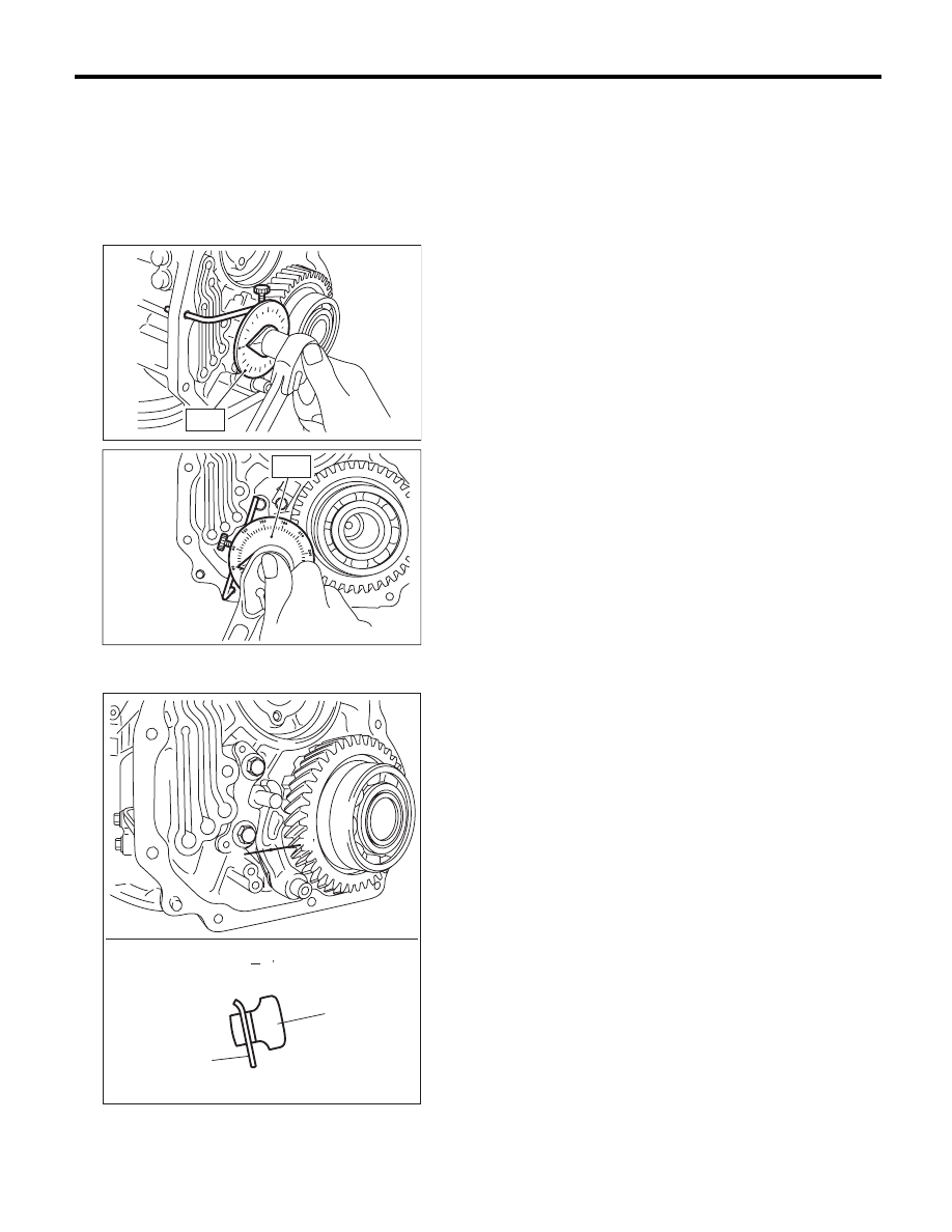
Parking Pawl
AUTOMATIC TRANSMISSION
4) Using the ST, tighten the bolts which tightened in
step 3) with specified angle.
Tightening angle:
17°
r
2°
ST
18854AA000
ANGLE GAUGE
NOTE:
Do not use extension as much as possible.
5) Make sure that the return spring is sticking out of
the parking pole hole.
6) Install the front vehicle speed sensor. <Ref. to
5AT-53, INSTALLATION, Front Vehicle Speed
Sensor.>
7) Install the center differential carrier. <Ref. to
5AT-77, INSTALLATION, Center Differential Carri-
er.>
8) Install the extension case. <Ref. to 5AT-68, IN-
STALLATION, Extension Case.>
9) Install the transmission assembly to the vehicle.
<Ref. to 5AT-43, INSTALLATION, Automatic
Transmission Assembly.>
C: INSPECTION
Make sure that the tab of parking pawl on reduction
driven gear is not worn or otherwise damaged.
(A) Parking pawl
(B) Return spring
AT-02071
ST
AT-02072
ST
AT-03370
B
(A)
(B)
B
B
B
5AT-81
Converter Case
AUTOMATIC TRANSMISSION
31.Converter Case
A: REMOVAL
1) Remove the transmission assembly from vehicle
body. <Ref. to 5AT-39, REMOVAL, Automatic
Transmission Assembly.>
2) Remove the torque converter assembly. <Ref. to
5AT-67, REMOVAL, Torque Converter Assembly.>
3) Remove the transmission harness connector
from stay.
4) Remove the turbine speed sensor 1. <Ref. to
5AT-56, REMOVAL, Turbine Speed Sensor 1.>
5) Remove the oil charge pipe. <Ref. to 5AT-66,
REMOVAL, Oil Charge Pipe.>
6) Remove the ATF inlet and outlet pipes. <Ref. to
5AT-62, REMOVAL, ATF Cooler Pipe and Hose.>
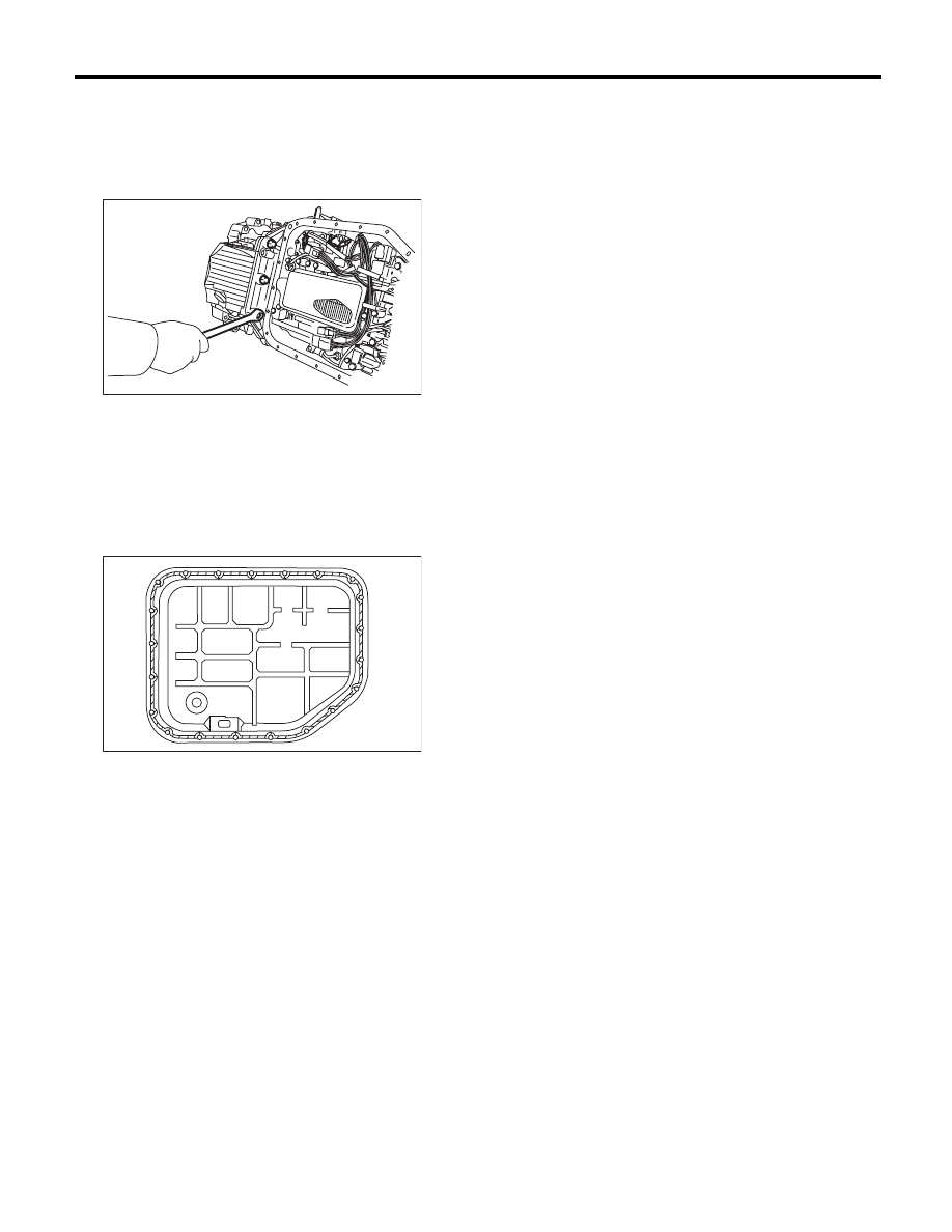
7) Remove the converter case attachment bolts.
8) Lay along the transmission body, and then re-
move the oil pan.
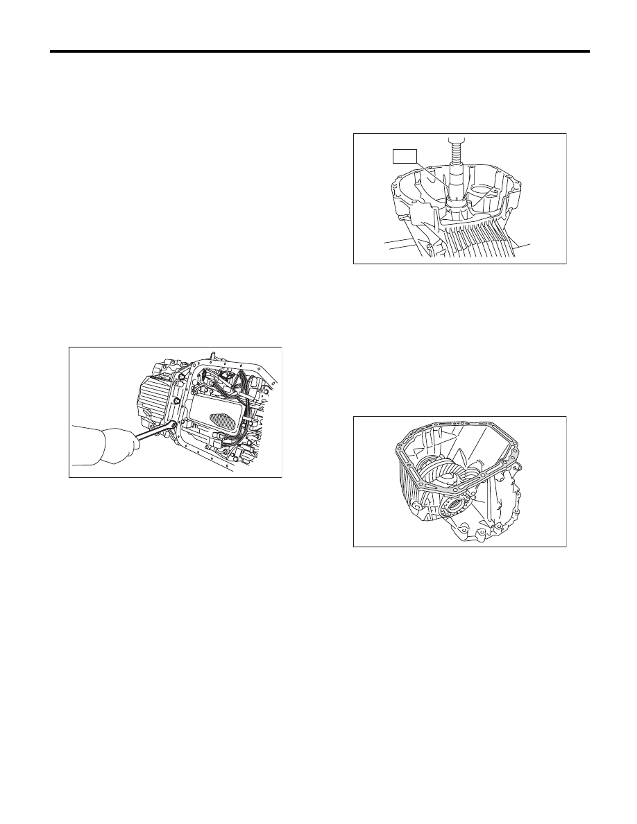
9) Remove the three converter case mounting bolts
(TORX
®
).
ST
18676AA020
TORX
®
WRENCH
10) Separate the converter case by lightly tapping
with plastic hammer.
11) Remove the front differential assembly. <Ref.
to 5AT-92, REMOVAL, Front Differential Assem-
bly.>
12) Remove the oil seal from converter case.
B: INSTALLATION
1) Check the appearance of each component and
clean them.
2) Press-fit the oil seal to converter case using ST.
ST
499587100
OIL SEAL INSTALLER
3) Install the front differential assembly to the case.
<Ref. to 5AT-92, INSTALLATION, Front Differen-
tial Assembly.>
4) Install the right and left side retainers. <Ref. to
5AT-96, ADJUSTMENT, Front Differential Assem-
bly.>
5) Apply proper amount of liquid gasket to the en-
tire matching surface of converter case.
Liquid gasket:
THREE BOND 1215 (Part No. 004403007) or
equivalent
6) Install the converter case assembly without
damaging bushing and oil seal.
NOTE:
Use new bolts for the oil charge pipe and ATF cool-
er pipe.
Tightening torque:
Oil charge pipe and ATF cooler pipe
38 N·m (3.9 kgf-m, 28.0 ft-lb)
Other than above
41 N·m (4.2 kgf-m, 30.2 ft-lb)
AT-04224
AT-01979
ST
AT-01975
5AT-82
Converter Case
AUTOMATIC TRANSMISSION
7) Install the three converter case mounting bolts
(TORX
®
).
ST
18676AA020
TORX
®
WRENCH
Tightening torque:
41 N·m (4.2 kgf-m, 30.2 ft-lb)
8) Apply proper amount of liquid gasket to the en-
tire oil pan mating surface, and then install it.
Liquid gasket:
THREE BOND 1217B (Part No. K0877YA020)
or equivalent
Tightening torque:
5 N·m (0.5 kgf-m, 3.7 ft-lb)
9) Install the transmission harness connector to the
stay.
10) Install the air breather hose. <Ref. to 5AT-65,
INSTALLATION, Air Breather Hose.>
11) Install the ATF cooler pipe. <Ref. to 5AT-63, IN-
STALLATION, ATF Cooler Pipe and Hose.>
12) Install the oil charge pipe with O-ring. <Ref. to
5AT-66, INSTALLATION, Oil Charge Pipe.>
13) Install the torque converter assembly. <Ref. to
5AT-67, INSTALLATION, Torque Converter As-
sembly.>
14) Install the transmission assembly to the vehi-
cle. <Ref. to 5AT-43, INSTALLATION, Automatic
Transmission Assembly.>
C: INSPECTION
Measure the backlash, and then adjust it to be with-
in standard values. <Ref. to 5AT-90, ADJUST-
MENT, Drive Pinion Shaft Assembly.>
AT-04224
AT-03249
5AT-83
Oil Pump Cover
AUTOMATIC TRANSMISSION
32.Oil Pump Cover
A: REMOVAL
1) Remove the transmission assembly from vehicle
body. <Ref. to 5AT-39, REMOVAL, Automatic
Transmission Assembly.>
2) Pull out the torque converter assembly. <Ref. to
5AT-67, REMOVAL, Torque Converter Assembly.>
3) Remove the transmission harness connector
from stay.
4) Remove the oil charge pipe. <Ref. to 5AT-66,
REMOVAL, Oil Charge Pipe.>
5) Remove the ATF inlet and outlet pipes. <Ref. to
5AT-62, REMOVAL, ATF Cooler Pipe and Hose.>
6) Separate the converter case and transmission
case. <Ref. to 5AT-81, REMOVAL, Converter
Case.>
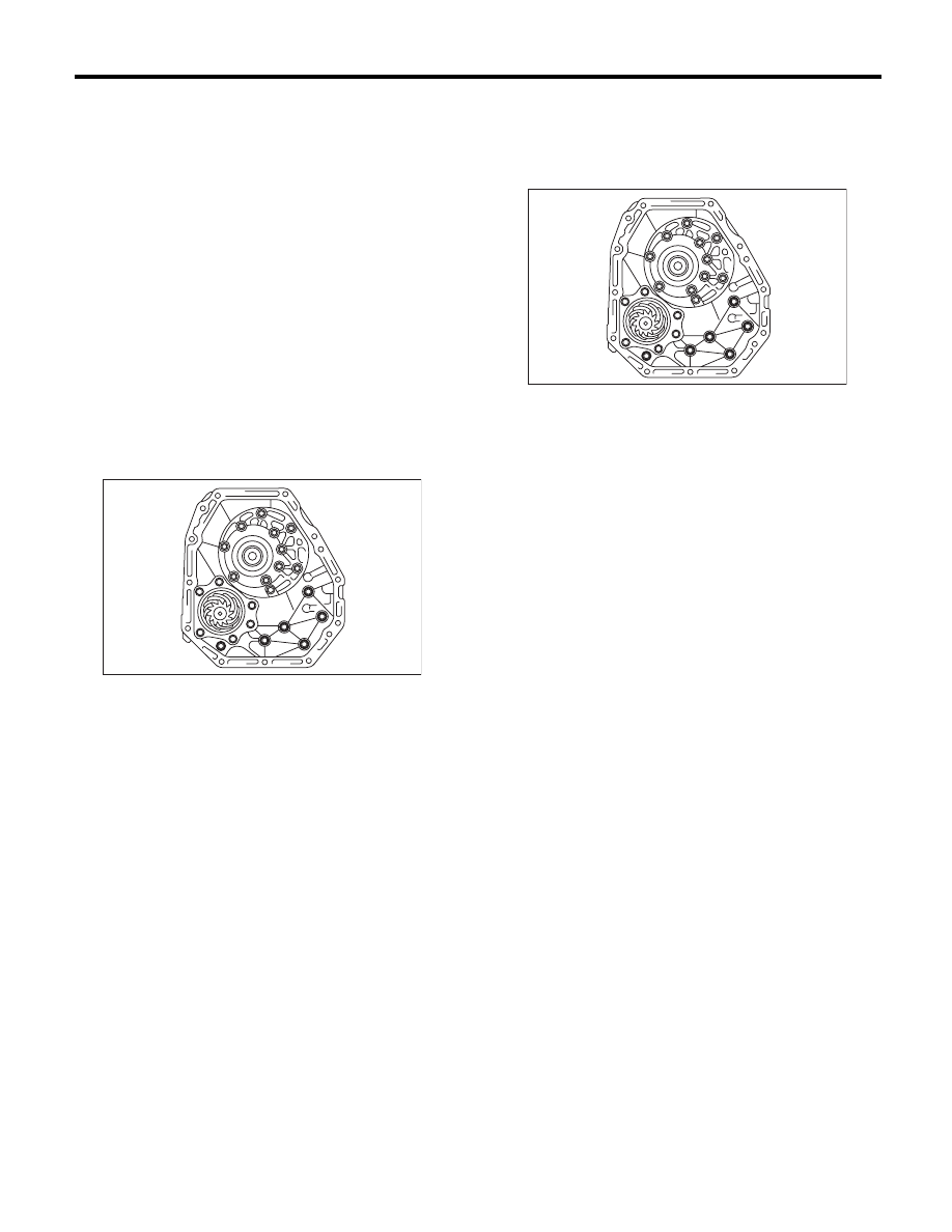
7) Remove the oil pump cover mounting bolt, and
then separate the oil pump cover from the AT main
case by lightly tapping with plastic hammer.
B: INSTALLATION
1) Secure the oil pump cover.
Tightening torque:
41 N·m (4.2 kgf-m, 30.2 ft-lb)
2) Install the converter case assembly to the trans-
mission case assembly. <Ref. to 5AT-81, INSTAL-
LATION, Converter Case.>
3) Install the transmission harness connector to the
stay.
4) Install the ATF cooler pipe. <Ref. to 5AT-63, IN-
STALLATION, ATF Cooler Pipe and Hose.>
5) Install the oil charge pipe together with an O-
ring. <Ref. to 5AT-66, INSTALLATION, Oil Charge
Pipe.>
6) Install the torque converter assembly. <Ref. to
5AT-67, INSTALLATION, Torque Converter As-
sembly.>
7) Install the transmission assembly to the vehicle.
<Ref. to 5AT-43, INSTALLATION, Automatic
Transmission Assembly.>
AT-01976
AT-01976
Нет комментариевНе стесняйтесь поделиться с нами вашим ценным мнением.
Текст