Subaru Legacy IV (2008 year). Service manual — part 1048
LI-9
Stop Light System
LIGHTING SYSTEM
7. Stop Light System
A: WIRING DIAGRAM
1. STOP LIGHT
<Ref. to WI-133, WIRING DIAGRAM, Stop Light
System.>
B: INSPECTION
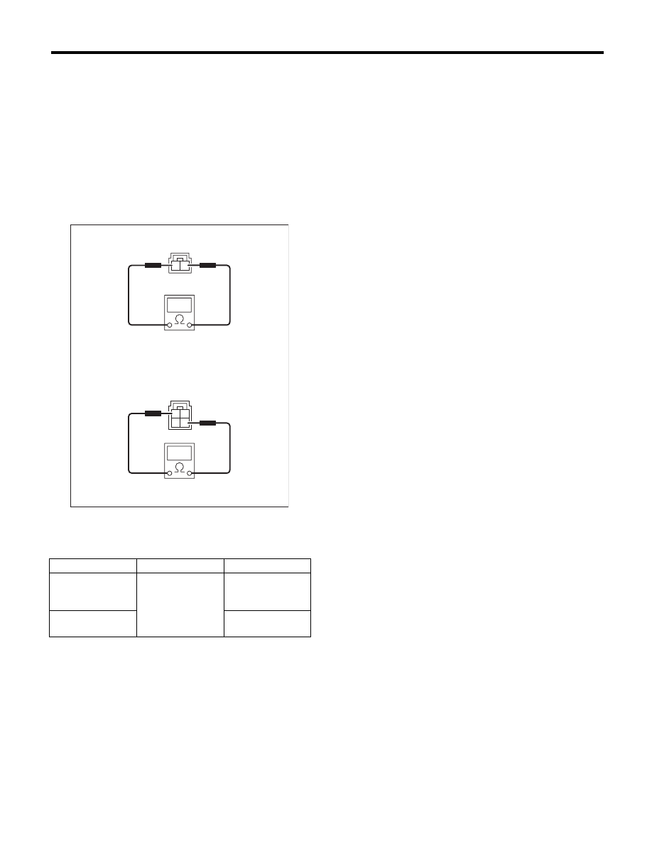
1. STOP LIGHT SWITCH
Measure the resistance between stop light switch
terminals.
(1) Models without cruise control
(2) Models with cruise control
Switch position
Terminal No.
Standard
When brake pedal
is depressed
Models without
cruise control:
1 and 2
Less than 1
:
When brake pedal
is released
Models with cruise
control: 2 and 3
1 M
: or more
LI-00265
3
4
1
2
1
2
(1)
(2)
LI-10
Room Light System
LIGHTING SYSTEM
8. Room Light System
A: WIRING DIAGRAM
1. ROOM LIGHT
<Ref. to WI-141, WIRING DIAGRAM, Interior Light
System.>
B: INSPECTION
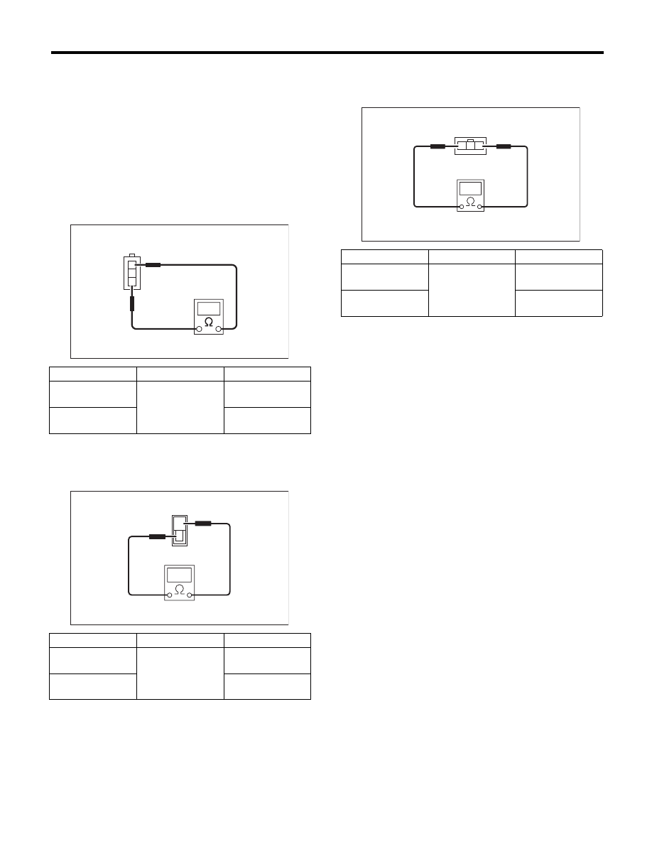
1. DOOR SWITCH
Measure the resistance between door switch termi-
nals.
2. REAR GATE LATCH SWITCH
Measure the resistance between rear gate latch
switch terminals.
3. TRUNK LID SWITCH
Measure the resistance between trunk lid switch
terminals.
Switch position
Terminal No.
Standard
When door is
opened
1 and 3
Less than 1
:
When door is
closed
1 M
: or more
Switch position
Terminal No.
Standard
When rear gate is
opened
1 and 2
Less than 1
:
When rear gate is
closed
1 M
: or more
1
2
3
LI-00007
LI-00276
1
2
Switch position
Terminal No.
Standard
When trunk lid is
opened
1 and 3
Less than 1
:
When trunk lid is
closed
1 M
: or more
LI-00277
1
2
3
LI-11
Combination Switch (Light)
LIGHTING SYSTEM
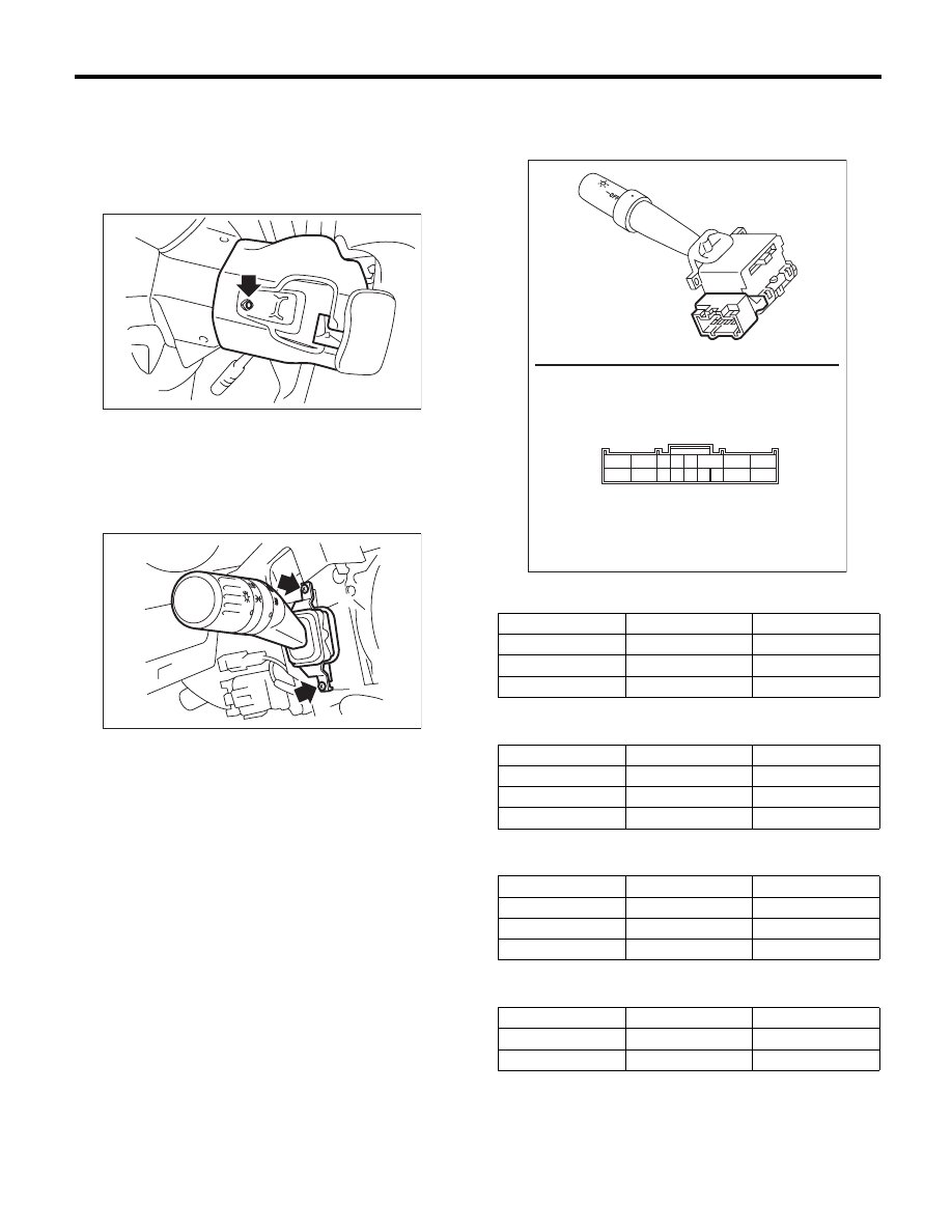
9. Combination Switch (Light)
A: REMOVAL
1) Disconnect the ground cable from the battery.
2) Remove the screws and remove the steering
column lower cover.
3) Remove the screws and steering column upper
cover.
4) Disconnect the connector from combination
switch.
5) Remove the screws which secure the switch,
then remove the combination switch.
B: INSTALLATION
Install in the reverse order of removal.
C: INSPECTION
Measure the resistance between combination
switch terminals.
1. LIGHTING SWITCH
2. DIMMER & PASSING SWITCH
3. TURN SIGNAL SWITCH
4. FRONT FOG LIGHT SWITCH
SL-00258
LI-00331
OFF
OFF
Switch position
Terminal No.
Standard
OFF
—
1 M
: or more
Tail
14 and 16
Less than 1
:
Head
13, 14 and 16
Less than 1
:
Switch position
Terminal No.
Standard
Passing
7, 8 and 16
Less than 1
:
Low beam
17 and 16
Less than 1
:
High beam
7 and 16
Less than 1
:
Switch position
Terminal No.
Standard
Left
1 and 2
Less than 1
:
Neutral
—
1 M
: or more
Right
2 and 3
Less than 1
:
Switch position
Terminal No.
Standard
OFF
—
1 M
: or more
ON
10 and 11
Less than 1
:
LI-00434
15 14 13 12 11 10
9
17
16
6 5 4
3
2
1
8
7
LI-12
Combination Base Switch Assembly
LIGHTING SYSTEM
10.Combination Base Switch
Assembly
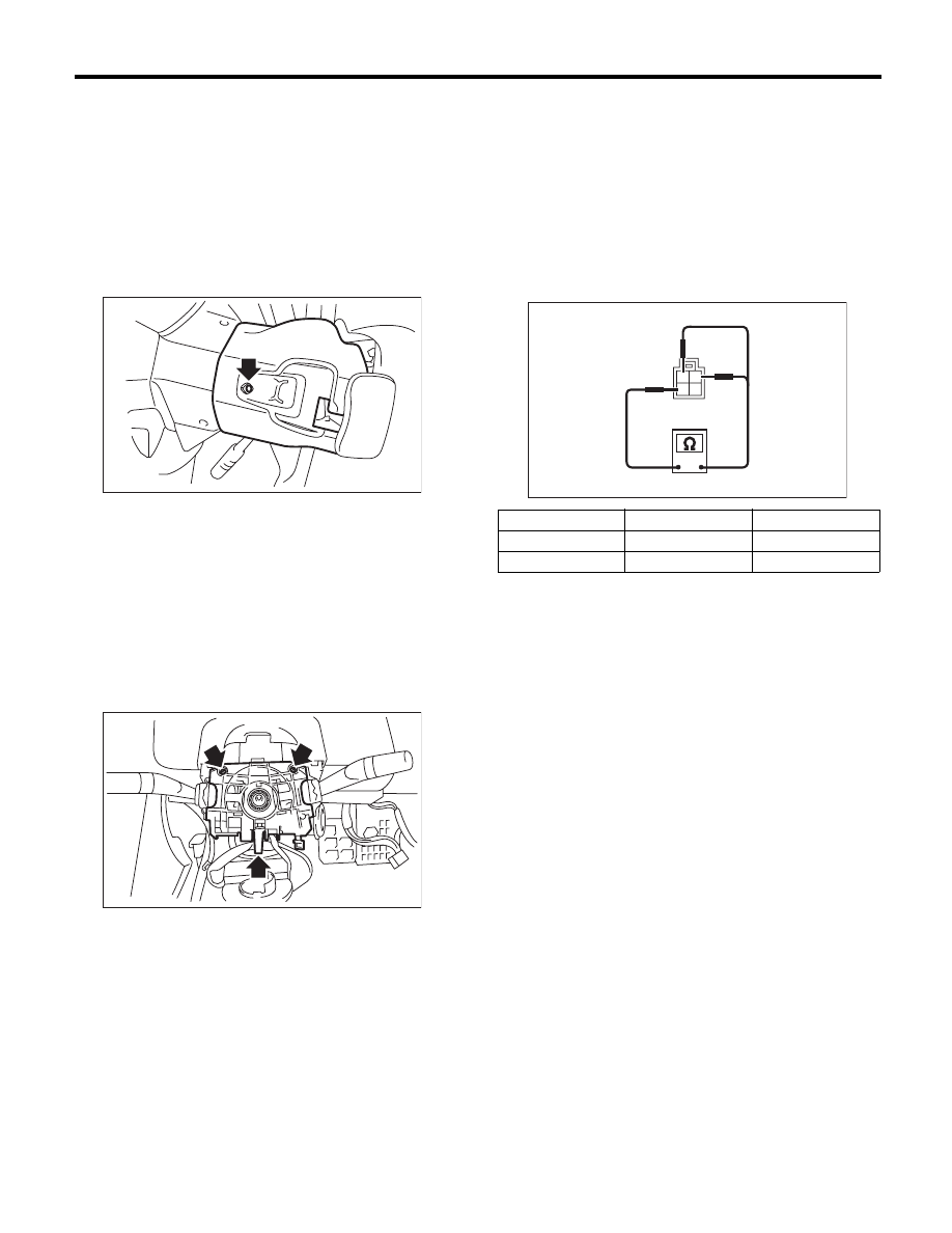
A: REMOVAL
1) Remove the driver’s airbag module. <Ref. to AB-
14, REMOVAL, Driver’s Airbag Module.>
2) Remove the steering wheel. <Ref. to PS-13, RE-
MOVAL, Steering Wheel.>
3) Remove the screws and remove the steering
column lower cover.
4) Remove the screws and steering column upper
cover.
5) On models equipped with paddle shifters, re-
move the paddle shift assembly. <Ref. to CS-33,
REMOVAL, Paddle Shift Assembly.>
6) Remove the combination switch. <Ref. to LI-11,
REMOVAL, Combination Switch (Light).> <Ref. to
WW-7, REMOVAL, Combination Switch (Wiper).>
7) Remove the four screws and remove the roll
connector.
8) Remove the three screws.
9) Disconnect the connector and remove the com-
bination base switch assembly.
B: INSTALLATION
1) Install in the reverse order of removal.
2) Before installing the steering wheel, be sure to
adjust the direction of roll connector with steering.
<Ref. to AB-25, ADJUSTMENT, Roll Connector.>
C: INSPECTION
1. COMBINATION BASE SWITCH
ASSEMBLY
Inspect the combination base switch assembly and
roll connector for cracks or deformation. If any
damage is found, replace with a new part.
2. PARKING SWITCH
Measure the resistance between parking switch
terminals.
SL-00258
LI-00271
Switch position
Terminal No.
Standard
OFF
2 and 4
Less than 1
:
ON
1 and 4
Less than 1
:
LI-00183
1
2
3
4
Нет комментариевНе стесняйтесь поделиться с нами вашим ценным мнением.
Текст