Subaru Legacy IV (2008 year). Service manual — part 1046
SB-22
Rear Seat Belt
SEAT BELT SYSTEM
LI-2
General Description
LIGHTING SYSTEM
1. General Description
A: SPECIFICATION
B: CAUTION
• Before removing or installing parts, always disconnect the battery ground cable from battery. When replac-
ing the audio, control module and other parts provided with memory functions, record the memory contents
before disconnecting the battery ground cable. Otherwise, the memory is cleared.
• Reassemble the parts in the reverse order of disassembly procedure unless otherwise indicated.
• Adjust parts to the given specifications.
• Connect the connectors securely during reassembly.
• After reassembly, make sure functional parts operate smoothly.
• The airbag system wiring harness is routed near electrical parts and switches. Airbag system wiring har-
nesses and connectors are yellow. Do not use the electrical test equipment on these circuits.
• Be careful not to damage the airbag system wiring harness when servicing electrical parts and switches.
C: PREPARATION TOOL
1. GENERAL TOOL
Headlight
Halogen type low beam
12 V — 55 W
Halogen type high beam
12 V — 60 W
Front turn signal, parking, front side marker light
12 V — 27/8 W
Front fog light
12 V — 55 W
Side turn signal light
12 V — 2.7 W (LED)
Rear combination light
Stop/tail light
12 V — 21/5 W
Turn signal light
12 V — 21 W
Wagon
Rear side marker light
12 V — 5 W
Back-up light
Sedan
12 V — 16 W
Wagon
12 V — 16 W
License plate light
12 V — 5 W
High-mounted stop light
Sedan
12 V — 21 W
Wagon
12 V — 1.3 W (LED)
Room light
12 V — 8 W
Spot map light
12 V — 8 W
Luggage room light
12 V — 13 W
Trunk room light
12 V — 5 W
Glove box light
12 V — 1.4 W
Door step light
12 V — 3 W
TOOL NAME
REMARKS
Circuit tester
Used for measuring resistance and voltage.
LI-3
Headlight and Tail Light System
LIGHTING SYSTEM
2. Headlight and Tail Light
System
A: WIRING DIAGRAM
1. HALOGEN TYPE HEADLIGHT
<Ref. to WI-128, WIRING DIAGRAM, Headlight
System.>
2. CLEARANCE LIGHT AND ILLUMINATION
LIGHT
<Ref. to WI-134, WIRING DIAGRAM, Clearance
Light and Illumination Light System.>
B: INSPECTION
1. HEADLIGHT SWITCH
Measure the resistance between headlight switch
terminals.
<Ref. to LI-11, INSPECTION, Combination Switch
(Light).>
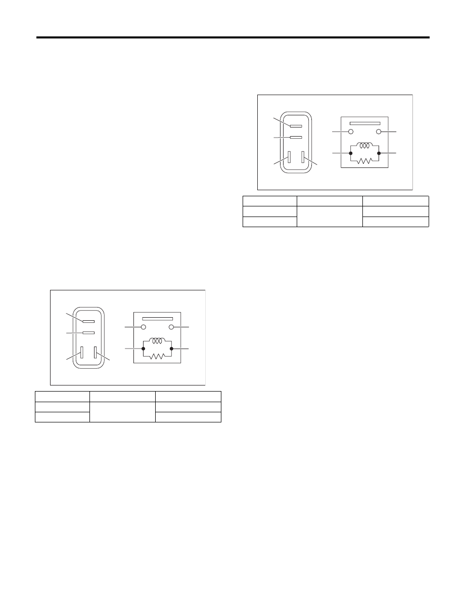
2. HEADLIGHT RELAY
Measure the headlight relay resistance between
terminals when connecting terminal No. 4 to the
battery positive terminal and terminal No. 3 to the
battery ground terminal.
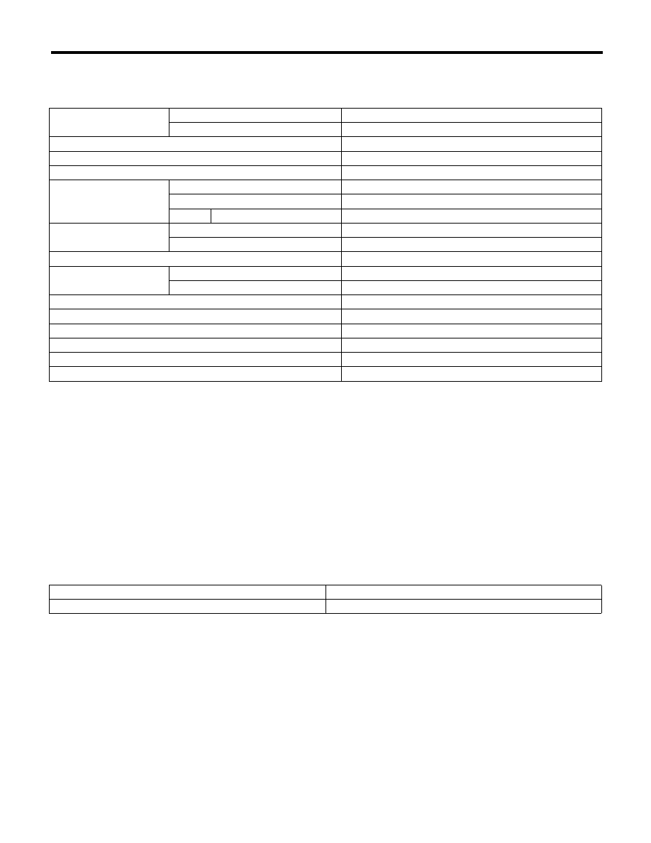
3. TAIL AND ILLUMINATION RELAY
Measure the resistance between the tail and illumi-
nation relay terminals when connecting terminal
No. 4 to the battery positive terminal and terminal
No. 3 to the battery ground terminal.
Continuity
Terminal No.
Standard
Yes
1 and 2
Less than 1
:
No
1 M
: or more
LI-00001
(1)
(2)
(1)
(4)
(2)
(3)
(3)
(4)
Continuity
Terminal No.
Standard
Yes
1 and 2
Less than 1
:
No
1 M
: or more
LI-00001
(1)
(2)
(1)
(4)
(2)
(3)
(3)
(4)

LI-4
Day Time Running Light System
LIGHTING SYSTEM
3. Day Time Running Light System
A: WIRING DIAGRAM
<Ref. to WI-128, WIRING DIAGRAM, Headlight System.>
B: INSPECTION
1. DAYTIME RUNNING LIGHT MODULE CHECK
Step
Check
Yes
No
1
CHECK POWER SUPPLY CIRCUIT.
1) Turn the ignition switch to ON.
2) Measure the voltage between the daytime
running light module terminal and chassis
ground.
Connector & terminal
(B96) No. 2 (+) — Chassis ground (–):
(B242) No. 6 (+) — Chassis ground (–):
Is the voltage battery voltage?
Go to step 2.
Check the fuse and
the power supply
circuit.
2
CHECK GROUND CIRCUIT.
1) Disconnect the daytime running light mod-
ule connector.
2) Measure the resistance between the day-
time running light module connector and chas-
sis ground.
Connector & terminal
(B242) No. 10 (+) — Chassis ground (–):
Is the resistance less than 1
:? Go to step 3.
Check the ground
circuit.
3
CHECK THE PARKING SIGNAL.
1) Connect the daytime running light module
connector.
2) Measure the voltage between the terminal
and chassis ground when pulling parking brake
lever and releasing.
Connector & terminal
(B96) No. 4 (+) — Chassis ground (–):
Does the voltage change to 0
battery voltage?
Go to step 4.
Check the parking
brake switch cir-
cuit.
4
CHECK THE STARTER SIGNAL.
Turn the ignition switch to ON
Starter and
measure the voltage of terminal.
Connector & terminal
(B96) No. 7 (+) — Chassis ground (–):
Does the voltage change to 0
battery voltage?
Go to step 5.
Check the starter
switch circuit.
5
CHECK THE HEADLIGHT SWITCH SIGNAL.
Turn the headlight switch to LO
OFF and
measure the voltage of terminal.
Connector & terminal
(B242) No. 2 (+) — Chassis ground (–):
Does the voltage change to 0
battery voltage?
Go to step 6.
Check the combi-
nation switch and
the headlight LO
circuit.
6
CHECK THE HEADLIGHT SWITCH SIGNAL.
Turn the headlight switch to HI
OFF and
measure the voltage of terminal.
Connector & terminal
(B96) No. 1 (+) — Chassis ground (–):
Does the voltage change to 0
battery voltage?
Go to step 7.
Check the combi-
nation switch and
the headlight HI
circuit.
7
CHECK THE HEADLIGHT SIGNAL.
1) Turn the ignition switch to ON.
2) Turn the headlight from HI to ON/OFF and
measure the voltage of terminal.
Connector & terminal
(B242) No. 5 (+) — Chassis ground (–):
Does the voltage change to 0
battery voltage?
Go to step 8.
Check the head-
light HI circuit.
8
CHECK THE HEADLIGHT SIGNAL.
1) Turn the ignition switch to ON.
2) Measure the voltage of terminal on passing
of headlight.
Connector & terminal
(B96) No. 3 (+) — Chassis ground (–):
Does the voltage change to 0
battery voltage?
If the above test is
OK, replace the
daytime running
light module.
Check the head-
light HI circuit.
Нет комментариевНе стесняйтесь поделиться с нами вашим ценным мнением.
Текст