Subaru Legacy IV (2008 year). Service manual — part 1047
LI-5
Day Time Running Light System
LIGHTING SYSTEM
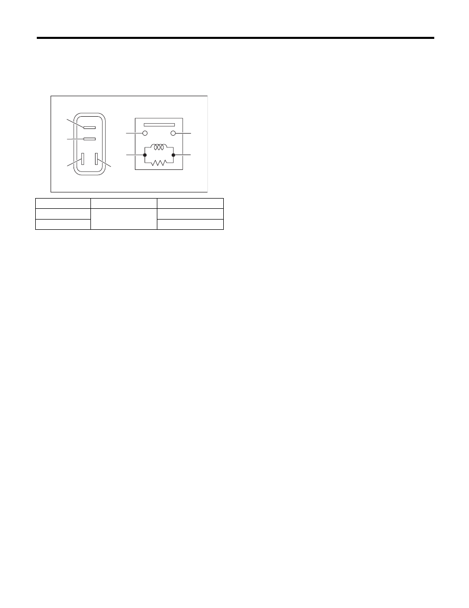
2. LOW BEAM RELAY
Measure the resistance between the daytime run-
ning relay terminals when connecting terminal No.
4 to the battery positive terminal and terminal No. 3
to the battery ground terminal.
Continuity
Terminal No.
Standard
Yes
1 and 2
Less than 1
:
No
1 M
: or more
LI-00001
(1)
(2)
(1)
(4)
(2)
(3)
(3)
(4)
LI-6
Front Fog Light System
LIGHTING SYSTEM
4. Front Fog Light System
A: WIRING DIAGRAM
1. FRONT FOG LIGHT
<Ref. to WI-131, WIRING DIAGRAM, Front Fog
Light System.>
B: INSPECTION
1. FRONT FOG LIGHT SWITCH
Measure the resistance between front fog light
switch terminals. <Ref. to LI-11, INSPECTION,
Combination Switch (Light).>
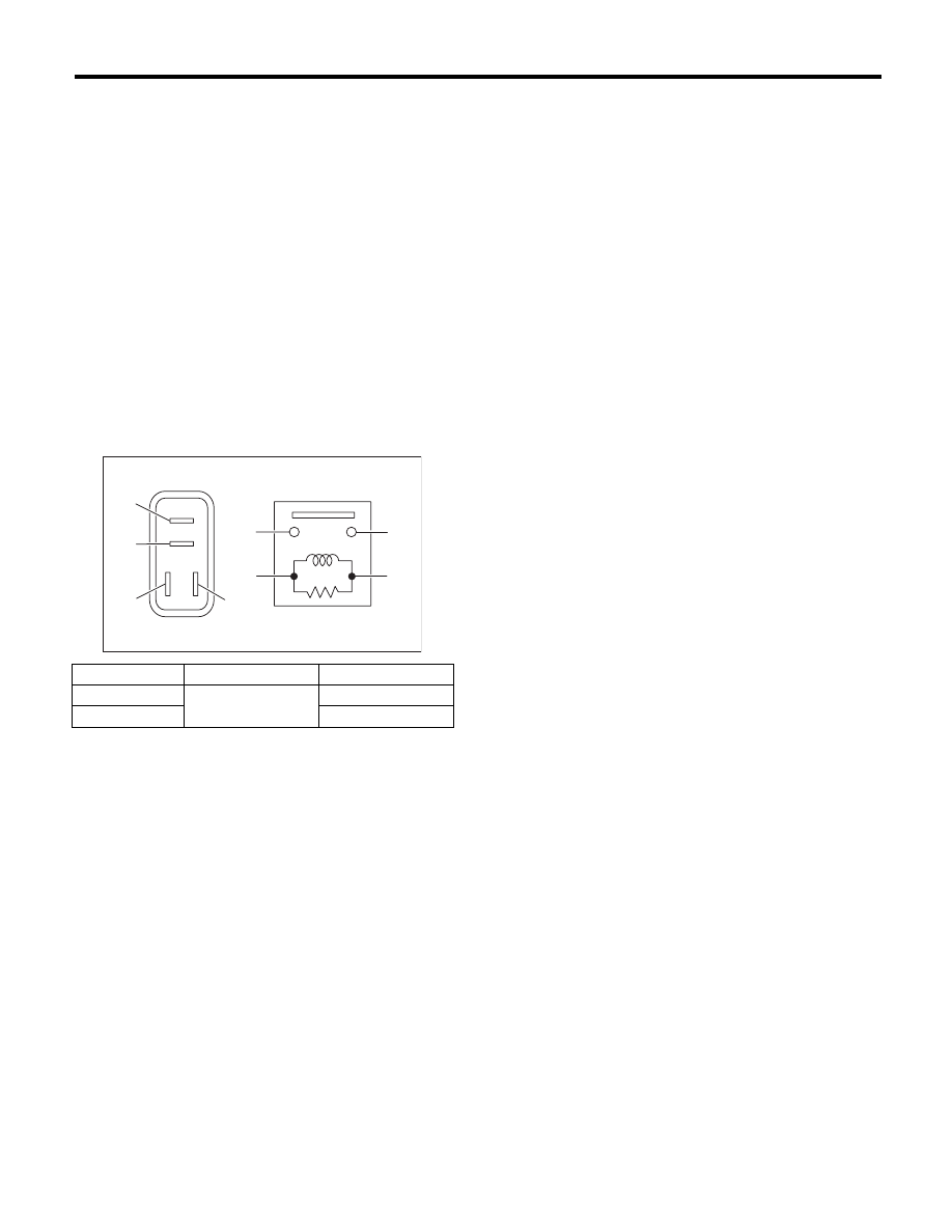
2. FRONT FOG LIGHT RELAY
Connect terminal No. 4 to battery positive terminal
and terminal No. 3 to battery ground terminal, and
measure the front fog light relay resistance be-
tween terminals.
Continuity
Terminal No.
Standard
Yes
1 and 2
Less than 1
:
No
1 M
: or more
LI-00001
(1)
(2)
(1)
(4)
(2)
(3)
(3)
(4)
LI-7
Turn Signal Light and Hazard Light System
LIGHTING SYSTEM
5. Turn Signal Light and Hazard
Light System
A: WIRING DIAGRAM
1. TURN SIGNAL LIGHT AND HAZARD
LIGHT
<Ref. to WI-139, WIRING DIAGRAM, Turn Signal
Light and Hazard Light System.>
B: INSPECTION
1. TURN SIGNAL SWITCH
Measure the resistance between turn signal switch
terminals. <Ref. to LI-11, INSPECTION, Combina-
tion Switch (Light).>
2. HAZARD SWITCH
Measure the resistance between hazard switch ter-
minals.
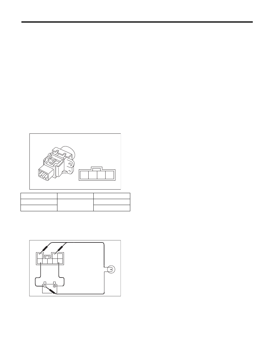
3. TURN SIGNAL AND HAZARD MODULE
Connect the battery and turn signal light bulb to the
module. The module is properly functioning if it
blinks when power is supplied to the circuit.
Switch position
Terminal No.
Standard
OFF
2 and 3
1 M
: or more
ON
Less than 1
:
LI-00261
4
3
2
1
LI-00262
3
2 1
8 7 6 5 4
LI-8
Back-up Light System
LIGHTING SYSTEM
6. Back-up Light System
A: WIRING DIAGRAM
1. BACK-UP LIGHT
<Ref. to WI-132, WIRING DIAGRAM, Back-up
Light System.>
B: INSPECTION
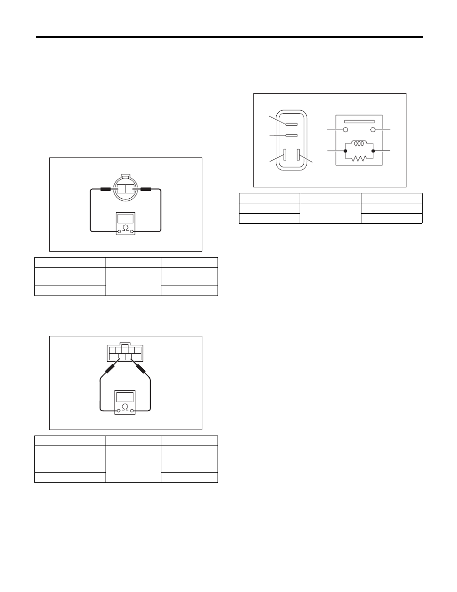
1. BACK-UP LIGHT SWITCH (MT MODEL)
Measure the resistance between the back-up light
switch terminals.
2. INHIBITOR SWITCH (4AT MODEL)
Measure the resistance between the inhibitor
switch terminals.
3. BACK-UP LIGHT RELAY (5AT MODEL)
Measure the resistance between headlight relay
terminals when connecting terminal No. 4 to the
battery positive terminal and terminal No. 3 to the
battery ground terminal.
NOTE:
Checks other than the back-up light relay. <Ref. to
4AT-46, INSPECTION, Inhibitor Switch.>
Switch position
Terminal No.
Standard
When shift lever is set
in reverse position
1 and 2
Less than 1
:
Other positions
1 M
: or more
Switch position
Terminal No.
Standard
When the selector
lever is in the “R”
range
7 and 8
Less than 1
:
Other positions
1 M
: or more
LI-00263
2
1
1
2
3
4
5
6
7
8
9
LI-00863
Continuity
Terminal No.
Standard
Yes
1 and 2
Less than 1
:
No
1 M
: or more
LI-00001
(1)
(2)
(1)
(4)
(2)
(3)
(3)
(4)
Нет комментариевНе стесняйтесь поделиться с нами вашим ценным мнением.
Текст