Subaru Legacy IV (2008 year). Service manual — part 936

VDC(diag)-59
Diagnostic Procedure with Diagnostic Trouble Code (DTC)
VEHICLE DYNAMICS CONTROL (VDC) (DIAGNOSTICS)
7
CHECK ECM SPECIFICATION.
Check the ECM specification.
Is the specification of ECM
same as vehicle specification?
Go to step 8.
Replace the ECM.
<Ref. to
FU(H4SO)-39,
Engine Control
Module (ECM).>
<Ref. to
FU(H4DOTC)-52,
Engine Control
Module (ECM).>
<Ref. to
FU(H6DO)-38,
Engine Control
Module (ECM).>
8
CHECK VDCCM&H/U.
1) Connect all connectors.
2) Clear the memory. <Ref. to VDC(diag)-23,
Clear Memory Mode.>
3) Perform the Inspection Mode. <Ref. to
VDC(diag)-22, Inspection Mode.>
4) Read the DTC.
Is the same DTC displayed?
Replace the
VDCCM only.
Go to step 9.
9
CHECK OTHER DTC DETECTION.
Is any other DTC displayed?
Perform the diag-
nosis according to
DTC. <Ref. to
VDC(diag)-34, List
of Diagnostic Trou-
ble Code (DTC).>
It results from a
temporary noise
interference.
Step
Check
Yes
No

VDC(diag)-60
Diagnostic Procedure with Diagnostic Trouble Code (DTC)
VEHICLE DYNAMICS CONTROL (VDC) (DIAGNOSTICS)
AB:DTC C0045 TCM MALFUNCTION
DTC DETECTING CONDITION:
Defective TCM
TROUBLE SYMPTOM:
• ABS does not operate.
• VDC does not operate.
Step
Check
Yes
No
1
CHECK AT SYSTEM.
1) Start the engine.
2) Check the DTC in AT system.
Is DTC of AT system displayed? Repair the AT sys-
tem.
Go to step 2.
2
CHECK VDCCM&H/U.
1) Connect all connectors.
2) Clear the memory. <Ref. to VDC(diag)-23,
Clear Memory Mode.>
3) Perform the Inspection Mode. <Ref. to
VDC(diag)-22, Inspection Mode.>
4) Read the DTC.
Is the same DTC displayed?
Replace the
VDCCM only.
Go to step 3.
3
CHECK OTHER DTC DETECTION.
Is any other DTC displayed?
Perform the diag-
nosis according to
DTC. <Ref. to
VDC(diag)-34, List
of Diagnostic Trou-
ble Code (DTC).>
It results from a
temporary noise
interference.
VDC(diag)-61
Diagnostic Procedure with Diagnostic Trouble Code (DTC)
VEHICLE DYNAMICS CONTROL (VDC) (DIAGNOSTICS)
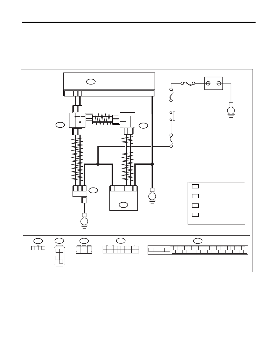
AC:DTC C0047 CAN COMMUNICATION
DTC DETECTING CONDITION:
CAN communication line circuit is open or shorted.
TROUBLE SYMPTOM:
• ABS does not operate.
• VDC does not operate.
WIRING DIAGRAM:
VDC00473
1 2 3 4
B310
VDCCM & H/U
25
10
35
B231
B230
2
4
1
1
4
2
3
3
STEERING
ANGLE
SENSOR
YAW RATE &
LATERAL G
SENSOR
E
E
B231
SBF-6
MAIN SBF
No.33
E
IGNITION
SWITCH
BATTERY
B310
4 5 6 7 8 9
26 27 28 29 30
2 3
1
31 32 33 34 35 36
10 11
14 15 16 17 18 19
37 38 39 40
12 13
41 42 43 44 45 46
20 21
23
24
22
25
B230
1
2
3
4
TWISTED PAIR LINE
TWISTED PAIR LINE
B365
B170
CAN
JOINT
CONNECTOR
4
*
3
*
4
3
*
*
2
1 :
:
*
*
CAN
JOINT
CONNECTOR
TERMINAL No. OPTIONAL
ARRANGEMENT AMONG
1, 2, 3,11,12 AND 13
TERMINAL No. OPTIONAL
ARRANGEMENT AMONG
8, 9, 10, 18, 19 AND 20
4
3 :
:
*
*
TERMINAL No. OPTIONAL
ARRANGEMENT AMONG
1, 2, 5 AND 6
TERMINAL No. OPTIONAL
ARRANGEMENT AMONG
3, 4, 7 AND 8
2
1
* *
2
1
* *
2
1
*
*
TWISTED
PAIR LINE
B170
3 4
5 6
1 2
7 8
1 2 3 4 5 6 7 8 9 10
11 12 13 14 15 16 17 18 19 20
B365

VDC(diag)-62
Diagnostic Procedure with Diagnostic Trouble Code (DTC)
VEHICLE DYNAMICS CONTROL (VDC) (DIAGNOSTICS)
Step
Check
Yes
No
1
CHECK LAN SYSTEM.
Perform the diagnosis for LAN system. <Ref. to
LAN(diag)-27, OPERATION, Read Diagnostic
Trouble Code (DTC).>
Is there any fault in LAN sys-
tem?
Perform the diag-
nosis according to
DTC for LAN sys-
tem.
Go to step 2.
2
CHECK POOR CONTACT IN CONNECTORS. Is there poor contact in
VDCCM&H/U connector?
Repair the connec-
tor.
Go to step 3.
3
CHECK OUTPUT OF STEERING ANGLE
SENSOR.
Connect the Subaru Select Monitor and check
output of the steering angle sensor.
Does the output signal change? Go to step 4.
Check output of
the steering angle
sensor. <Ref. to
VDC(diag)-81,
DTC C0071
STEER ANGLE
SENSOR OP,
Diagnostic Proce-
dure with Diagnos-
tic Trouble Code
(DTC).>
4
CHECK OUTPUT OF YAW RATE & LATERAL
G SENSOR.
Connect the Subaru Select Monitor and check
output of the yaw rate & lateral G sensor.
Does the output signal change? Go to step 5.
Check output of
the yaw rate & lat-
eral G sensor.
<Ref. to
VDC(diag)-94,
DTC C0072 YAW
RATE SENSOR
COMMUNICA-
TION, Diagnostic
Procedure with
Diagnostic Trouble
Code (DTC).>
5
CHECK VDCCM&H/U.
1) Connect all connectors.
2) Clear the memory. <Ref. to VDC(diag)-23,
Clear Memory Mode.>
3) Perform the Inspection Mode. <Ref. to
VDC(diag)-22, Inspection Mode.>
4) Read the DTC.
Is the same DTC displayed?
Replace the
VDCCM only.
<Ref. to VDC-10,
REPLACEMENT,
VDC Control Mod-
ule and Hydraulic
Control Unit
(VDCCM&H/U).>
Temporary poor
contact occurs.
Нет комментариевНе стесняйтесь поделиться с нами вашим ценным мнением.
Текст