Subaru Legacy IV (2008 year). Service manual — part 935
VDC(diag)-55
Diagnostic Procedure with Diagnostic Trouble Code (DTC)
VEHICLE DYNAMICS CONTROL (VDC) (DIAGNOSTICS)
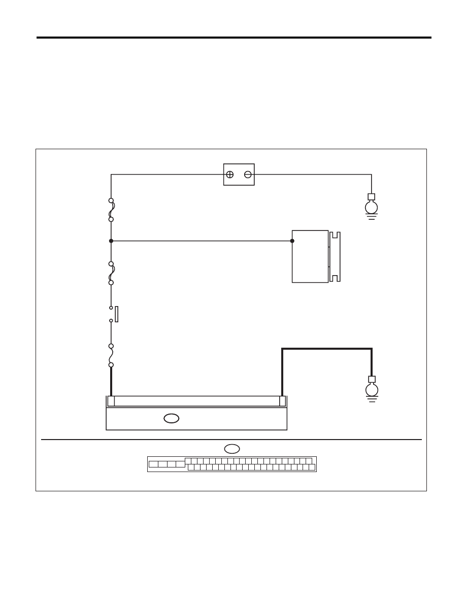
Y: DTC C0042 POWER SUPPLY VOLTAGE FAILURE
DTC DETECTING CONDITION:
Improper VDCCM&H/U power supply voltage
TROUBLE SYMPTOM:
• ABS does not operate.
• EBD may not operate.
• VDC does not operate.
NOTE:
Warning lights go off if voltage returns.
WIRING DIAGRAM:
MAIN SBF
SBF-6
No.33
B310
E
E
25
28
VDCCM & H/U
BATTERY
GENERATOR
IGNITION
SWITCH
B310
4 5 6 7 8 9
26 27 28 29 30
2 3
1
31 32 33 34 35 36
10 11
14 15 16 17 18 19
37 38 39 40
12 13
41 42 43 44 45 46
20 21
23
24
22
25
VDC00463

VDC(diag)-56
Diagnostic Procedure with Diagnostic Trouble Code (DTC)
VEHICLE DYNAMICS CONTROL (VDC) (DIAGNOSTICS)
Step
Check
Yes
No
1
CHECK GENERATOR.
1) Start the engine.
2) Run the engine at idle after warming up.
3) Measure the voltage between generator ter-
minal B and chassis ground.
Terminals
Generator B terminal (+) — Chassis
ground (–):
Is the voltage 10 — 15 V?
Go to step 2.
Repair the genera-
tor.
2
CHECK BATTERY TERMINAL.
Turn the ignition switch to OFF.
Are the positive and negative
battery terminals clamped
tightly?
Go to step 3.
Tighten the termi-
nal.
3
CHECK VDCCM&H/U INPUT VOLTAGE.
1) Disconnect the connector from the
VDCCM&H/U.
2) Run the engine at idle.
3) Operate devices such as headlights, air
conditioner, defogger, etc. which produce an
electrical load.
4) Measure the voltage between VDCCM&H/U
connector and chassis ground.
Connector & terminal
(B310) No. 28 (+) — Chassis ground (–):
Is the voltage 10 — 15 V?
Go to step 4.
Repair the power
supply circuit.
4
CHECK VDCCM&H/U GROUND CIRCUIT.
1) Turn the ignition switch to OFF.
2) Measure the resistance between
VDCCM&H/U connector and chassis ground.
Connector & terminal
(B310) No. 25 — Chassis ground:
Is the resistance less than 0.5
:? Go to step 5.
Repair the
VDCCM&H/U
ground harness.
5
CHECK POOR CONTACT IN CONNECTORS. Is there poor contact in connec-
tor between generator, battery
and VDCCM&H/U?
Repair the connec-
tor.
Go to step 6.
6
CHECK VDCCM&H/U.
1) Connect all connectors.
2) Clear the memory. <Ref. to VDC(diag)-23,
Clear Memory Mode.>
3) Perform the Inspection Mode. <Ref. to
VDC(diag)-22, Inspection Mode.>
4) Read the DTC.
Is the same DTC displayed?
Replace the
VDCCM only.
<Ref. to VDC-10,
REPLACEMENT,
VDC Control Mod-
ule and Hydraulic
Control Unit
(VDCCM&H/U).>
Go to step 7.
7
CHECK OTHER DTC DETECTION.
Is any other DTC displayed?
Perform the diag-
nosis according to
DTC. <Ref. to
VDC(diag)-34, List
of Diagnostic Trou-
ble Code (DTC).>
Temporary poor
contact occurs.

VDC(diag)-57
Diagnostic Procedure with Diagnostic Trouble Code (DTC)
VEHICLE DYNAMICS CONTROL (VDC) (DIAGNOSTICS)
Z: DTC C0044 TCM COMMUNICATION CIRCUIT
DTC DETECTING CONDITION:
No CAN signal from TCM.
TROUBLE SYMPTOM:
• ABS does not operate.
• VDC does not operate.
Step
Check
Yes
No
1
CHECK LAN SYSTEM.
Perform the diagnosis for LAN system. <Ref. to
LAN(diag)-27, OPERATION, Read Diagnostic
Trouble Code (DTC).>
Is there any fault in LAN sys-
tem?
Perform the diag-
nosis according to
DTC for LAN sys-
tem.
Go to step 2.
2
CHECK POOR CONTACT IN CONNECTORS. Is there poor contact in TCM
connector?
Repair the connec-
tor.
Go to step 3.
3
CHECK TCM.
Is the TCM normal?
Go to step 4.
Replace the TCM.
<Ref. to 4AT-61,
Transmission Con-
trol Module
(TCM).> <Ref. to
5AT-60, Transmis-
sion Control Mod-
ule (TCM).>
4
CHECK VDCCM&H/U.
1) Connect all connectors.
2) Clear the memory. <Ref. to VDC(diag)-23,
Clear Memory Mode.>
3) Perform the Inspection Mode. <Ref. to
VDC(diag)-22, Inspection Mode.>
4) Read the DTC.
Is the same DTC displayed?
Replace the
VDCCM only.
Go to step 5.
5
CHECK OTHER DTC DETECTION.
Is any other DTC displayed?
Perform the diag-
nosis according to
DTC. <Ref. to
VDC(diag)-34, List
of Diagnostic Trou-
ble Code (DTC).>
It results from a
temporary noise
interference.

VDC(diag)-58
Diagnostic Procedure with Diagnostic Trouble Code (DTC)
VEHICLE DYNAMICS CONTROL (VDC) (DIAGNOSTICS)
AA:DTC C0045 INCORRECT VDC CONTROL MODULE SPECIFICATIONS
DTC DETECTING CONDITION:
Different control module specification
TROUBLE SYMPTOM:
• ABS does not operate.
• VDC does not operate.
NOTE:
When parameter selection for VDCCM is improper, this DTC may be memorized.
Step
Check
Yes
No
1
CHECK VDCCM REPLACEMENT HISTORY. Is there replacement history of
VDCCM alone?
Go to step 2.
Go to step 3.
2
CHECK VDCCM IDENTIFICATION NUMBER.
Check the identification number on the sticker
attached on the VDCCM side.
AT:
T3 (2.5 L turbo models and OUTBACK 3.0 L
models)
T7 (Sedan 3.0L with 18 inch tire model)
TA (2.5L non-turbo model and sedan 3.0L
with 17 inch tire model)
MT:
T4 (2.5L turbo model)
TB (2.5L non-turbo model)
Is the identification number cor-
rect?
Go to step 4.
Replace the
VDCCM only.
3
CHECK VDCCM&H/U IDENTIFICATION
NUMBER.
Check the identification number stamped on the
upper side of the H/U.
AT:
T3 (2.5 L turbo models and OUTBACK 3.0 L
models)
T7 (Sedan 3.0L with 18 inch tire model)
TA (2.5L non-turbo model and sedan 3.0L
with 17 inch tire model)
MT:
T4 (2.5L turbo model)
TB (2.5L non-turbo model)
Is the identification number cor-
rect?
Go to step 4.
Replace the
VDCCM&H/U.
4
CHECK PARAMETER SELECTED FOR VDC-
CM.
<Ref. to VDC(diag)-17, PARAMETER CHECK,
OPERATION, Subaru Select Monitor.>
Does the parameter registered
to the VDCCM match with the
target vehicle?
Go to step 5.
Select and register
the correct param-
eter. <Ref. to
VDC(diag)-16,
PARAMETER
SELECTION,
OPERATION, Sub-
aru Select Moni-
tor.>
5
CHECK TCM SPECIFICATION.
Check the TCM specification.
Is the specification of TCM
same as vehicle specification?
Go to step 6.
Replace the TCM.
<Ref. to 4AT-61,
Transmission Con-
trol Module
(TCM).> <Ref. to
5AT-60, Transmis-
sion Control Mod-
ule (TCM).>
6
CHECK AT SYSTEM.
1) Start the engine.
2) Check the DTC in AT system.
Is DTC of AT system displayed? Repair the AT sys-
tem.
Go to step 7.
Нет комментариевНе стесняйтесь поделиться с нами вашим ценным мнением.
Текст