Subaru Legacy IV (2008 year). Service manual — part 934

VDC(diag)-51
Diagnostic Procedure with Diagnostic Trouble Code (DTC)
VEHICLE DYNAMICS CONTROL (VDC) (DIAGNOSTICS)
Step
Check
Yes
No
1
CHECK VDCCM&H/U INPUT VOLTAGE.
1) Turn the ignition switch to OFF.
2) Disconnect the connector from the
VDCCM&H/U.
3) Run the engine at idle.
4) Measure the voltage between VDCCM&H/U
connector and chassis ground.
Connector & terminal
(B310) No. 28 (+) — Chassis ground (–):
Is the voltage 10 — 15 V?
Go to step 2.
Repair the power
supply circuit.
2
CHECK VDCCM&H/U GROUND CIRCUIT.
1) Turn the ignition switch to OFF.
2) Measure the resistance between
VDCCM&H/U connector and chassis ground.
Connector & terminal
(B310) No. 25 — Chassis ground:
Is the resistance less than 0.5
:? Go to step 3.
Repair the
VDCCM&H/U
ground harness.
3
CHECK POOR CONTACT IN CONNECTORS. Is there poor contact in connec-
tor between generator, battery
and VDCCM&H/U?
Repair the connec-
tor.
Go to step 4.
4
CHECK VDCCM&H/U.
1) Connect all connectors.
2) Clear the memory. <Ref. to VDC(diag)-23,
Clear Memory Mode.>
3) Perform the Inspection Mode. <Ref. to
VDC(diag)-22, Inspection Mode.>
4) Read the DTC.
Is the same DTC displayed?
Replace the
VDCCM&H/U.
<Ref. to VDC-7,
VDC Control Mod-
ule and Hydraulic
Control Unit
(VDCCM&H/U).>
Go to step 5.
5
CHECK OTHER DTC DETECTION.
Is any other DTC displayed?
Perform the diag-
nosis according to
DTC. <Ref. to
VDC(diag)-34, List
of Diagnostic Trou-
ble Code (DTC).>
Temporary poor
contact occurs.
VDC(diag)-52
Diagnostic Procedure with Diagnostic Trouble Code (DTC)
VEHICLE DYNAMICS CONTROL (VDC) (DIAGNOSTICS)
W: DTC C0041 ECM
DTC DETECTING CONDITION:
Defective VDCCM&H/U
TROUBLE SYMPTOM:
• ABS does not operate.
• EBD does not operate.
• VDC does not operate.
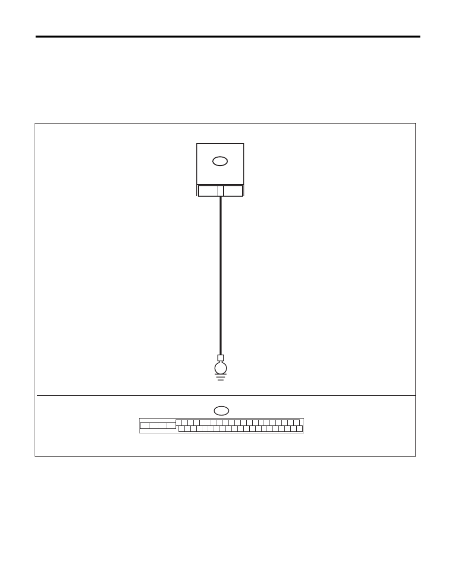
WIRING DIAGRAM:
VDCCM & H/U
25
B310
E
B310
4 5 6 7 8 9
26 27 28 29 30
2 3
1
31 32 33 34 35 36
10 11
14 15 16 17 18 19
37 38 39 40
12 13
41 42 43 44 45 46
20 21
23
24
22
25
VDC00464

VDC(diag)-53
Diagnostic Procedure with Diagnostic Trouble Code (DTC)
VEHICLE DYNAMICS CONTROL (VDC) (DIAGNOSTICS)
Step
Check
Yes
No
1
CHECK VDCCM&H/U GROUND CIRCUIT.
1) Turn the ignition switch to OFF.
2) Disconnect the connector from the
VDCCM&H/U.
3) Measure the resistance between
VDCCM&H/U and chassis ground.
Connector & terminal
(B310) No. 25 — Chassis ground:
Is the resistance less than 0.5
:? Go to step 2.
Repair the
VDCCM&H/U
ground harness.
2
CHECK POOR CONTACT IN CONNECTORS. Is there poor contact of the con-
nector between the battery, igni-
tion switch and VDCCM&H/U?
Repair the connec-
tor.
Go to step 3.
3
CHECK CAUSE OF SIGNAL NOISE.
Are the radio wave devices and
electronic components
installed correctly?
Go to step 4.
Install the radio
wave devices and
electronic compo-
nents properly.
4
CHECK CAUSE OF SIGNAL NOISE.
Is there a noise source (such as
an antenna) installed near the
sensor harness?
Install the noise
source apart from
the sensor har-
ness.
Go to step 5.
5
CHECK VDCCM&H/U.
1) Connect all connectors.
2) Clear the memory. <Ref. to VDC(diag)-23,
Clear Memory Mode.>
3) Perform the Inspection Mode. <Ref. to
VDC(diag)-22, Inspection Mode.>
4) Read the DTC.
Is the same DTC displayed?
Replace the
VDCCM only.
<Ref. to VDC-10,
REPLACEMENT,
VDC Control Mod-
ule and Hydraulic
Control Unit
(VDCCM&H/U).>
Go to step 6.
6
CHECK OTHER DTC DETECTION.
Is any other DTC displayed?
Perform the diag-
nosis according to
DTC. <Ref. to
VDC(diag)-34, List
of Diagnostic Trou-
ble Code (DTC).>
Temporary poor
contact occurs.

VDC(diag)-54
Diagnostic Procedure with Diagnostic Trouble Code (DTC)
VEHICLE DYNAMICS CONTROL (VDC) (DIAGNOSTICS)
X: DTC C0041 PARAMETER SELECTION ERROR
DTC DETECTING CONDITION:
VDCCM parameter selection failure
TROUBLE SYMPTOM:
• ABS does not operate.
• EBD does not operate.
• VDC does not operate.
NOTE:
When the VDCCM or VDCCM&H/U is replaced, this DTC may be memorized.
Step
Check
Yes
No
1
CHECK VDCCM&H/U REPLACEMENT HIS-
TORY.
Is there replacement history of
VDCCM alone?
Go to step 2.
Go to step 3.
2
CHECK VDCCM IDENTIFICATION NUMBER.
Check the identification number on the sticker
attached on the VDCCM side.
AT:
T3 (2.5 L turbo models and OUTBACK 3.0 L
models)
T7 (Sedan 3.0L with 18 inch tire model)
TA (2.5L non-turbo model and sedan 3.0L
with 17 inch tire model)
MT:
T4 (2.5L turbo model)
TB (2.5L non-turbo model)
Is the identification number cor-
rect?
Go to step 4.
Replace the
VDCCM only.
3
CHECK VDCCM&H/U IDENTIFICATION
NUMBER.
Check the identification number stamped on the
upper side of the H/U.
AT:
T3 (2.5 L turbo models and OUTBACK 3.0 L
models)
T7 (Sedan 3.0L with 18 inch tire model)
TA (2.5L non-turbo model and sedan 3.0L
with 17 inch tire model)
MT:
T4 (2.5L turbo model)
TB (2.5L non-turbo model)
Is the identification number cor-
rect?
Go to step 4.
Replace the
VDCCM&H/U.
4
CHECK PARAMETER SELECTED FOR VDC-
CM.
<Ref. to VDC(diag)-17, PARAMETER CHECK,
OPERATION, Subaru Select Monitor.>
Does the parameter registered
to the VDCCM match with the
target vehicle?
Replace the
VDCCM only.
Select and register
the correct param-
eter. <Ref. to
VDC(diag)-16,
PARAMETER
SELECTION,
OPERATION, Sub-
aru Select Moni-
tor.>
Нет комментариевНе стесняйтесь поделиться с нами вашим ценным мнением.
Текст