Subaru Legacy IV (2008 year). Service manual — part 937
VDC(diag)-63
Diagnostic Procedure with Diagnostic Trouble Code (DTC)
VEHICLE DYNAMICS CONTROL (VDC) (DIAGNOSTICS)
AD:DTC C0051 VALVE RELAY
DTC DETECTING CONDITION:
Defective valve relay
TROUBLE SYMPTOM:
• ABS does not operate.
• EBD does not operate.
• VDC does not operate.
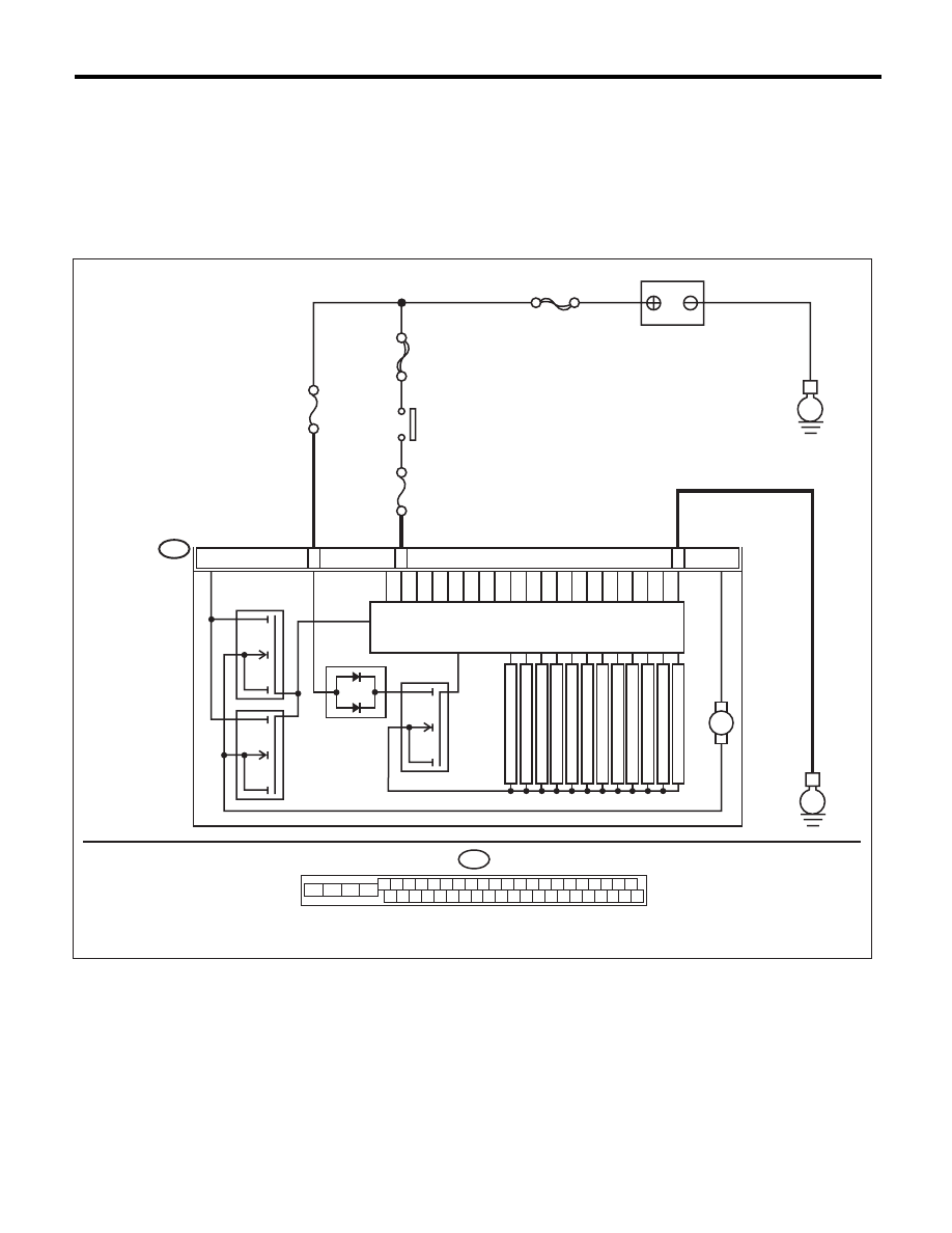
WIRING DIAGRAM:
B310
E
24
25
VDCCM & H/U
28
PUMP MOTOR
M
FL INLET
MAIN SBF
SBF-6
No.1
No.33
E
BATTERY
IGNITION
SWITCH
SOLENOID VALVE
FR INLET
RL INLET
RR INLET
FL OUTLET
FR OUTLET
RL OUTLET
RR OUTLET
PRIMARY CUT
SECONDARY CUT
PRIMARY SUCTION
MOTOR RELAY
VALVE RELAY
SECONDARY SUCTION
B310
4 5 6 7 8 9
26 27 28 29 30
2 3
1
31 32 33 34 35 36
10 11
14 15 16 17 18 19
37 38 39 40
12 13
41 42 43 44 45 46
20 21
23
24
22
25
VDC00466

VDC(diag)-64
Diagnostic Procedure with Diagnostic Trouble Code (DTC)
VEHICLE DYNAMICS CONTROL (VDC) (DIAGNOSTICS)
Step
Check
Yes
No
1
CHECK VDCCM&H/U INPUT VOLTAGE.
1) Turn the ignition switch to OFF.
2) Disconnect the connector from the
VDCCM&H/U.
3) Run the engine at idle.
4) Measure the voltage between VDCCM&H/U
connector and chassis ground.
Connector & terminal
(B310) No. 28 (+) — Chassis ground (–):
(B310) No. 24 (+) — Chassis ground (–):
Is the voltage 10 — 15 V?
Go to step 2.
Repair the power
supply circuit.
2
CHECK VDCCM&H/U INPUT VOLTAGE.
Calculate the voltage difference measured in
step 1.
A: (B310) No. 28 (+) — Chassis ground (–):
B: (B310) No. 24 (+) — Chassis ground (–):
Is the voltage difference
between A and B 2 V or more?
Repair the power
supply circuit.
Go to step 3.
3
CHECK VDCCM&H/U GROUND CIRCUIT.
1) Turn the ignition switch to OFF.
2) Measure the resistance between
VDCCM&H/U connector and chassis ground.
Connector & terminal
(B310) No. 25 — Chassis ground:
Is the resistance less than 0.5
:? Go to step 4.
Repair the
VDCCM&H/U
ground harness.
4
CHECK VDCCM&H/U VALVE RELAY.
Measure the resistance between VDCCM&H/U
connector terminals.
Connector & terminal
(B310) No. 24 — (B310) No. 25:
Is the resistance 1 M
: or
more?
Go to step 5.
Replace the
VDCCM&H/U.
5
CHECK POOR CONTACT IN CONNECTORS. Is there poor contact in connec-
tor between generator, battery
and VDCCM&H/U?
Repair the connec-
tor.
Go to step 6.
6
CHECK VDCCM&H/U.
1) Connect all connectors.
2) Clear the memory. <Ref. to VDC(diag)-23,
Clear Memory Mode.>
3) Perform the Inspection Mode. <Ref. to
VDC(diag)-22, Inspection Mode.>
4) Read the DTC.
Is the same DTC displayed?
Replace the
VDCCM only.
<Ref. to VDC-10,
REPLACEMENT,
VDC Control Mod-
ule and Hydraulic
Control Unit
(VDCCM&H/U).>
Go to step 7.
7
CHECK OTHER DTC DETECTION.
Is any other DTC displayed?
Perform the diag-
nosis according to
DTC. <Ref. to
VDC(diag)-34, List
of Diagnostic Trou-
ble Code (DTC).>
Temporary poor
contact occurs.
VDC(diag)-65
Diagnostic Procedure with Diagnostic Trouble Code (DTC)
VEHICLE DYNAMICS CONTROL (VDC) (DIAGNOSTICS)
AE:DTC C0052 MOTOR AND MOTOR RELAY OFF FAILURE
DTC DETECTING CONDITION:
• Defective motor and motor relay
• Defective harness connector
TROUBLE SYMPTOM:
• ABS does not operate.
• VDC does not operate.
• EBD may not operate.
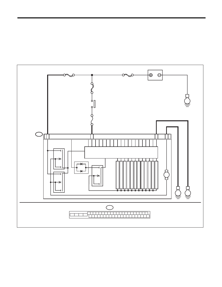
WIRING DIAGRAM:
B310
E
23
25
VDCCM & H/U
28
PUMP MOTOR
M
FL INLET
MAIN SBF
SBF-6
No.33
E
BATTERY
IGNITION
SWITCH
SOLENOID VALVE
MOTOR RELAY
VALVE RELAY
FR INLET
RL INLET
RR INLET
FL OUTLET
FR OUTLET
RL OUTLET
RR OUTLET
PRIMARY CUT
SECONDARY CUT
PRIMARY SUCTION
SBF-1
E
22
SECONDARY SUCTION
B310
4 5 6 7 8 9
26 27 28 29 30
2 3
1
31 32 33 34 35 36
10 11
14 15 16 17 18 19
37 38 39 40
12 13
41 42 43 44 45 46
20 21
23
24
22
25
VDC00467

VDC(diag)-66
Diagnostic Procedure with Diagnostic Trouble Code (DTC)
VEHICLE DYNAMICS CONTROL (VDC) (DIAGNOSTICS)
Step
Check
Yes
No
1
CHECK VDCCM&H/U INPUT VOLTAGE.
1) Turn the ignition switch to OFF.
2) Disconnect the connector from the
VDCCM&H/U.
3) Turn the ignition switch to ON.
4) Measure the voltage between VDCCM&H/U
connector and chassis ground.
Connector & terminal
(B310) No. 23 (+) — Chassis ground (–):
(B310) No. 28 (+) — Chassis ground (–):
Is the voltage 10 — 15 V?
Go to step 2.
Repair the
VDCCM&H/U
power supply cir-
cuit.
2
CHECK INSTALLATION OF MOTOR
GROUND.
Is the motor ground terminal
installation bolt tightened 33 N·m
(3.4 kgf-m, 24.3 ft-lb)?
Go to step 3.
Tighten the motor
ground terminal
installation bolt.
3
CHECK VDCCM&H/U GROUND CIRCUIT.
1) Turn the ignition switch to OFF.
2) Measure the resistance between
VDCCM&H/U connector and chassis ground.
Connector & terminal
(B310) No. 25 — Chassis ground:
(B310) No. 22 — Chassis ground:
Is the resistance less than 0.5
:? Go to step 4.
Repair the
VDCCM&H/U
ground harness.
4
CHECK VDCCM&H/U MOTOR RELAY.
Measure the resistance between VDCCM&H/U
connector terminals.
Terminals
No. 23 — No. 22:
Is the resistance 1 M
: or
more?
Go to step 5.
Replace the
VDCCM&H/U.
5
CHECK POOR CONTACT IN CONNECTORS.
Turn the ignition switch to OFF.
Is there poor contact in connec-
tor between generator, battery
and VDCCM&H/U?
Repair the connec-
tor.
Go to step 6.
6
CHECK VDCCM&H/U.
1) Connect all connectors.
2) Clear the memory. <Ref. to VDC(diag)-23,
Clear Memory Mode.>
3) Perform the Inspection Mode. <Ref. to
VDC(diag)-22, Inspection Mode.>
4) Read the DTC.
Is the same DTC displayed?
Replace the
VDCCM&H/U.
<Ref. to VDC-7,
VDC Control Mod-
ule and Hydraulic
Control Unit
(VDCCM&H/U).>
Go to step 7.
7
CHECK OTHER DTC DETECTION.
Is any other DTC displayed?
Perform the diag-
nosis according to
DTC. <Ref. to
VDC(diag)-34, List
of Diagnostic Trou-
ble Code (DTC).>
Temporary poor
contact occurs.
NOTE:
Though the ABS
warning light re-
mains on at this
time, this is normal.
Drive the vehicle at
12 km/h (7 MPH)
or more in order to
turn ABS warning
light off. Be sure to
drive the vehicle
and check that the
warning light goes
off.
Нет комментариевНе стесняйтесь поделиться с нами вашим ценным мнением.
Текст