Subaru Legacy III (2000-2003 year). Service manual — part 224
EN(H4SOw/oOBD)-86
ENGINE (DIAGNOSTICS)
DIAGNOSTIC PROCEDURE WITH DIAGNOSTIC TROUBLE CODE (DTC)
K: DTC 35 PURGE CONTROL SOLENOID VALVE
• DIAGNOSIS:
• The purge control solenoid valve is not in function.
• The harness connector between ECM and purge control solenoid valve is in short or open.
• TROUBLE SYMPTOM:
• Erroneous idling
CAUTION:
After repair or replacement of faulty parts, conduct CLEAR MEMORY and INSPECTION MODES. <Ref.
to EN(H4SOw/oOBD)-28, OPERATION, Clear Memory Mode.> and <Ref. to EN(H4SOw/oOBD)-26, OP-
ERATION, Inspection Mode.>
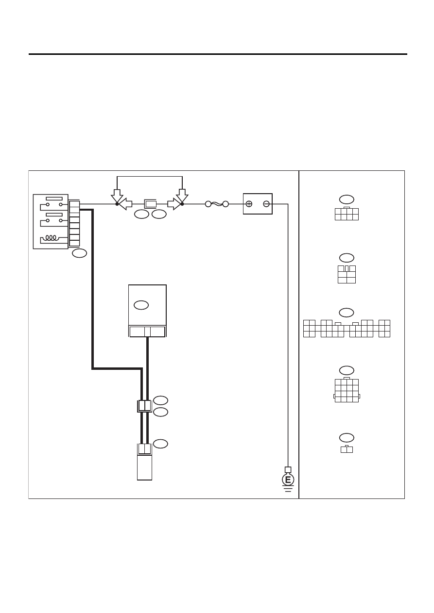
• WIRING DIAGRAM:
EN-01059
F44
B61
PURGE CONTROL
SOLENOID VALVE
E4
B22
E3
B47
B47
3
4
1
2
5
6
B134
1 2
3 4
5 6
7 8
9 10 11 12 13 14 15 16 17 18 19 20 21 22 23
24 25
26 27 28 29
30 31 32 33
34 35
B22
1 2 3 4
5 6 7 8
9 10 11 12
13 14 15 16
E4
F44
SBF-5
BATTERY
MAIN RELAY
1
2
3
5
4
6
6
LHD
LHD
RHD
RHD
2
2
1
3
2
B134
ECM
1 2 3 4
5 6 7 8
1 2

EN(H4SOw/oOBD)-87
ENGINE (DIAGNOSTICS)
DIAGNOSTIC PROCEDURE WITH DIAGNOSTIC TROUBLE CODE (DTC)
Step
Value
Yes
No
1
CHECK OPERATION SOUND OF PURGE
CONTROL SOLENOID VALVE.
1) Turn ignition switch to OFF.
2) Connect test mode connector.
3) Turn ignition switch to ON.
4) Make sure that the ON/OFF operating
sound of purge control solenoid valve
occurs at about 10 Hz.
Does purge control solenoid valve produce
operating sound?
The valve produces operating
sound.
2
CHECK POOR CONTACT.
Check poor contact in ECM connector.
Is there poor contact in ECM connector?
There is poor contact.
Repair poor con-
tact in ECM.
Replace ECM.
<Ref. to
FU(H4SOw/
oOBD)-42, Engine
Control Module.>
3
CHECK HARNESS BETWEEN PURGE CON-
TROL SOLENOID VALVE AND ECM CON-
NECTOR.
1) Turn ignition switch to OFF.
2) Disconnect test mode connector.
3) Disconnect connector from purge control
solenoid valve.
4) Turn ignition switch to ON.
5) Measure voltage between ECM and chas-
sis ground.
Connector & terminal
(B134) No. 2 (+) — Chassis ground (–):
Does the measured value exceed the spec-
ified value?
10 V
Repair battery
short circuit in har-
ness between
ECM and purge
control solenoid
valve connector.
After repair,
replace ECM.
4
CHECK HARNESS BETWEEN PURGE CON-
TROL SOLENOID VALVE AND ECM CON-
NECTOR.
1) Turn ignition switch to OFF.
2) Disconnect connector from ECM.
3) Measure resistance of harness between
ECM and purge control solenoid valve of
harness connector.
Connector & terminal
(B134) No. 2 — (E4) No. 2:
Is the measured value less than the speci-
fied value?
1
Ω
Repair open circuit
in harness
between ECM and
purge control sole-
noid valve connec-
tor.
5
CHECK PURGE CONTROL SOLENOID
VALVE.
1) Remove purge control solenoid valve.
2) Measure resistance between purge control
solenoid valve terminals.
Terminals
No. 1 — No. 2:
Is the measured value within the specified
value?
23 — 27
Ω
Replace purge
control solenoid
valve. <Ref. to
EC(H4SOw/
oOBD)-8, Purge
Control Solenoid
Valve.>

EN(H4SOw/oOBD)-88
ENGINE (DIAGNOSTICS)
DIAGNOSTIC PROCEDURE WITH DIAGNOSTIC TROUBLE CODE (DTC)
6
CHECK POWER SUPPLY TO PURGE CON-
TROL SOLENOID VALVE.
1) Turn ignition switch to ON.
2) Measure voltage between purge control
solenoid valve and engine ground.
Connector & terminal
(E4) No. 1 (+) — Engine ground (
−−−−
):
Does the measured value exceed the spec-
ified value?
10 V
Repair harness
and connector.
NOTE:
In this case, repair
the following:
• Open circuit in
harness between
main relay and
purge control sole-
noid valve connec-
tor
• Poor contact in
main relay con-
nector
• Poor contact in
coupling connector
(B22)
7
CHECK POOR CONTACT.
Check poor contact in purge control solenoid
valve connector.
Is there poor contact in purge control solenoid
valve connector?
There is poor contact.
Repair poor con-
tact in purge con-
trol solenoid valve
connector.
Contact with your
Subaru distributor.
NOTE:
Inspection by your
Subaru distributor
is required, be-
cause probable
cause is deteriora-
tion of multiple
parts.
Step
Value
Yes
No
EN(H4SOw/oOBD)-89
ENGINE (DIAGNOSTICS)
DIAGNOSTIC PROCEDURE WITH DIAGNOSTIC TROUBLE CODE (DTC)
L: DTC 38 TORQUE CONTROL SIGNAL
• DIAGNOSIS:
• Abnormal signal entered from TCM
• The harness connector between ECM and TCM is in short.
CAUTION:
After repair or replacement of faulty parts, conduct CLEAR MEMORY and INSPECTION MODES. <Ref.
to EN(H4SOw/oOBD)-28, OPERATION, Clear Memory Mode.> and <Ref. to EN(H4SOw/oOBD)-26, OP-
ERATION, Inspection Mode.>
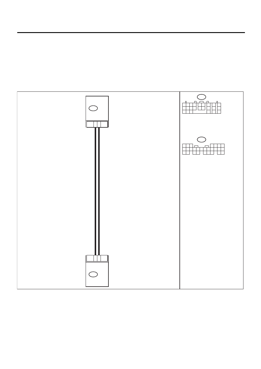
• WIRING DIAGRAM:
EN-01060
TCM
16
17
5
B135
B56
14
B56
B135
ECM
5 6 7
8
2
1
9
4
3
10
24
22 23
25
11 12 13 14 15
26
27 28
16 17 18 19
20 21
1 2
7
8
9
5 6
3 4
10 11 12
19 20 21
13
14 15
16
17
18
22
23
24
Нет комментариевНе стесняйтесь поделиться с нами вашим ценным мнением.
Текст