Subaru Legacy III (2000-2003 year). Service manual — part 223

EN(H4SOw/oOBD)-82
ENGINE (DIAGNOSTICS)
DIAGNOSTIC PROCEDURE WITH DIAGNOSTIC TROUBLE CODE (DTC)
Step
Value
Yes
No
1
CHECK FOR OTHER CAUSES AFFECTING
EXHAUST GAS.
1) Check for use of improper fuel.
2) Check if engine oil or coolant level is
extremely low.
Does CO% after warm-up exceed the spec-
ified value?
2%
Check fuel sys-
tem.
2
CHECK EXHAUST SYSTEM.
Is there a fault in exhaust system?
The system is faulty.
Repair exhaust
system.
NOTE:
• Loose installa-
tion of front portion
of exhaust pipe
onto cylinder
heads
• Loose connec-
tion between front
exhaust pipe and
front catalytic con-
verter
• Damage of
exhaust pipe
resulting in hole
3
CHECK INPUT VOLTAGE FOR OXYGEN
SENSOR.
1) Disconnect connector from oxygen sensor
connector.
2) Measure voltage between main relay and
oxygen sensor.
Connector & terminal
(B18) No. 2 (+) — Chassis ground (
−−−−
):
Does the measured value exceed the spec-
ified value?
10 V
Repair open circuit
between main
relay and oxygen
sensor.
4
CHECK HARNESS CONNECTOR BETWEEN
OXYGEN SENSOR AND ENGINE GROUND
TERMINAL.
Measure resistance between oxygen sensor
and chassis ground.
Connector & terminal
(B18) No. 1 — Chassis ground:
Is the measured value less than the specified
value?
1
Ω
Repair open circuit
between oxygen
sensor and chas-
sis ground.
5
CHECK OXYGEN SENSOR.
Measure resistance between oxygen sensor
terminals.
Connector & terminal
No. 1 — No. 2:
Is the measured value less than the specified
value?
30
Ω
Repair poor con-
tact.
6
CHECK HARNESS BETWEEN ECM AND OX-
YGEN SENSOR.
1) Disconnect connector from ECM.
2) Measure resistance between ECM and
chassis ground.
Connector & terminal
(B136) No. 7 — Chassis ground:
Does the measured value exceed the spec-
ified value?
1 M
Ω
Repair ground
short circuit
between ECM and
chassis ground.

EN(H4SOw/oOBD)-83
ENGINE (DIAGNOSTICS)
DIAGNOSTIC PROCEDURE WITH DIAGNOSTIC TROUBLE CODE (DTC)
7
CHECK HARNESS BETWEEN ECM AND OX-
YGEN SENSOR.
1) Ignition switch to ON.
2) Measure voltage between ECM and chas-
sis ground.
Connector & terminal
(B136) No. 7 (+) — Chassis ground (–):
Does the measured value exceed the spec-
ified value?
0.2 V
Repair battery
short circuit
between ECM and
oxygen sensor.
8
CHECK INPUT VOLTAGE FOR ECM.
1) Turn ignition switch OFF.
2) Warm up engine until coolant temperature
exceed 70
°
C (158
°
F) and idle.
3) Set plus (+) probe to ECM connector termi-
nal, and set minus (
−
) probe to chassis
ground.
Connector & terminal
(B136) No. 7 (+) — Chassis ground (
−−−−
):
4) Measure voltage between ECM and chas-
sis ground.
Is the measured waveform standard?
0.1
←
→
1 V
Replace oxygen
sensor.
9
CHECK POOR CONTACT.
Check poor contact in ECM connector.
Is there poor contact in ECM connector?
There is poor contact.
Replace oxygen
sensor connector.
Replace ECM.
<Ref. to
FU(H4SOw/
oOBD)-42, Engine
Control Module.>
Step
Value
Yes
No
EN(H4SOw/oOBD)-84
ENGINE (DIAGNOSTICS)
DIAGNOSTIC PROCEDURE WITH DIAGNOSTIC TROUBLE CODE (DTC)
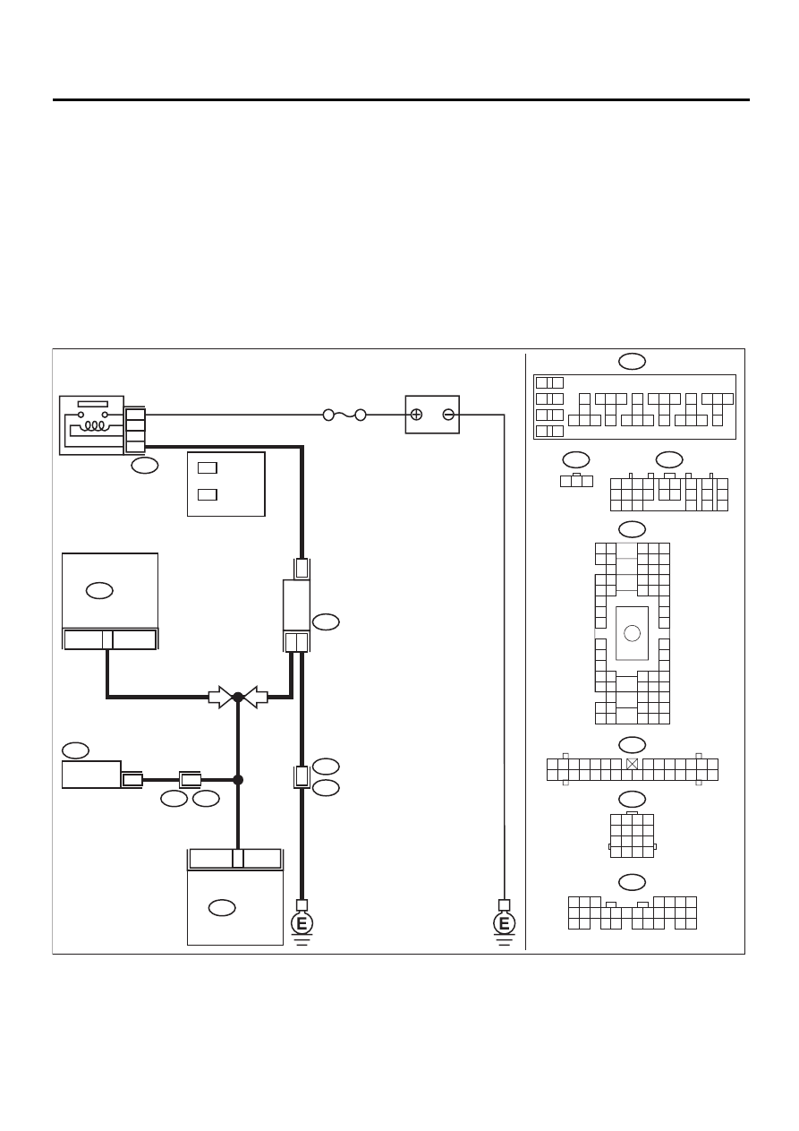
J: DTC 33 VEHICLE SPEED SIGNAL
• DIAGNOSIS:
• The vehicle speed signal is abnormal.
• The harness connector between ECM and vehicle speed sensor is in short or open.
• TROUBLE SYMPTOM:
• Erroneous idling
• Engine stalls.
• Poor driving performance
CAUTION:
After repair or replacement of faulty parts, conduct CLEAR MEMORY and INSPECTION MODES. <Ref.
to EN(H4SOw/oOBD)-28, OPERATION, Clear Memory Mode.> and <Ref. to EN(H4SOw/oOBD)-26, OP-
ERATION, Inspection Mode.>
• WIRING DIAGRAM:
EN-01058
B36
i1
i10
B157
B17
B56
B36
i10
B22
B135
BATTERY
E4
13
24
ECM
COMBINATION
METER
VEHICLE
SPEED
SENSOR
3
1
2
B17
B135
17
TCM
B56
IGNITION
RELAY
No. 5
B157
B22
E3
16
MT
AT
1 2 3
1 2 3 4
5 6 7 8
9 10 11 12
13 14 15 16
1 2 3 4 5 6 7
8 9 10 11 12 13 14
15 16 17 18 19 20 21 22 23 24 25 26 27 28 29 30
5 6 7
8
2
1
9
4
3
10
24
22 23
25
11 12 13 14 15
26
27 28
16 17 18 19
20 21
1 2
7
8
9
5 6
3 4
10 11 12
19 20 21
13
14 15
16
17
18
22
23
24
B4 B5 B6
A4 A5 A6
C5 C6
F6
D4 D5 D6
F1
H1
C4
G6
G1
C2
K1
M1 M2
K6
L1
D1 D2
A1 A2
B1 B2
I6
J6
L2
I1
J1
H6
M4 M5 M6
L4 L5 L6
N5 N6
O4 O5 O6
N4
P4 P5
N2
O1 O2
P1 P2
N3
O3
P3
P6
A3
B3
C3
E4 E5 E6
E1 E2
10
11 12 13
14 15 16
17
18
19
20
21 22 23
24 25 26
27
28
29
30
31 32 33
34 35 36
37
38
1
2
9
3
4
5
6
7
8
1
*
2
*
1
*
2
*
LHD : 9
RHD : 38
LHD : 10
RHD : 37

EN(H4SOw/oOBD)-85
ENGINE (DIAGNOSTICS)
DIAGNOSTIC PROCEDURE WITH DIAGNOSTIC TROUBLE CODE (DTC)
Step
Value
Yes
No
1
CHECK SPEEDOMETER OPERATION IN
COMBINATION METER.
Does speedometer operate normally?
Speedometer operates nor-
mally.
Check speedome-
ter and vehicle
speed sensor.
2
CHECK INPUT SIGNAL FOR ECM.
1) Lift-up the vehicle.
2) Set the positive (+) terminal and earth lead
of oscilloscope at ECM connector terminals
and chassis ground.
Connector & terminal
(B135) No. 24 (+) — Chassis ground (–):
3) Start the engine.
4) Shift on the gear position, and put the vehi-
cle at constant speed.
5) Measure signal voltage indicated on oscillo-
scope.
Does the measured value exceed the spec-
ified value?
3 V
3
CHECK POOR CONTACT.
Check poor contact in ECM connector.
Is there poor contact in ECM connector?
There is poor contact.
Repair poor con-
tact in ECM.
Replace ECM.
<Ref. to
FU(H4SOw/
oOBD)-42, Engine
Control Module.>
4
CHECK HARNESS BETWEEN ECM AND
COMBINATION METER CONNECTOR.
Measure voltage between ECM and chassis
ground.
Connector & terminal
(B135) No. 24 (+) — Chassis ground (
−−−−
):
Does the measured value exceed the specified
value?
2 V
Repair harness
and connector.
NOTE:
In this case, repair
the following:
Battery short cir-
cuit in harness
between ECM and
combination meter
connector
5
CHECK HARNESS BETWEEN ECM AND
COMBINATION METER CONNECTOR.
1) Turn ignition switch to OFF.
2) Measure resistance of harness between
ECM connector and chassis ground.
Connector & terminal
(B135) No. 24 — Chassis ground:
Is the measured value less than the speci-
fied value?
10
Ω
Repair ground
short circuit in har-
ness between
ECM and combi-
nation meter con-
nector.
6
CHECK POOR CONTACT.
Check poor contact in ECM connector.
Is there poor contact in ECM connector?
There is poor contact.
Repair poor con-
tact in ECM.
Replace ECM.
<Ref. to
FU(H4SOw/
oOBD)-42, Engine
Control Module.>
Нет комментариевНе стесняйтесь поделиться с нами вашим ценным мнением.
Текст