Subaru Legacy III (2000-2003 year). Service manual — part 222

EN(H4SOw/oOBD)-78
ENGINE (DIAGNOSTICS)
DIAGNOSTIC PROCEDURE WITH DIAGNOSTIC TROUBLE CODE (DTC)
6
CHECK HARNESS BETWEEN ECM AND IN-
TAKE AIR TEMPERATURE SENSOR CON-
NECTOR.
Measure resistance of harness between ECM
connector and chassis ground.
Connector & terminal
(B136) No. 13 — Chassis ground:
Does the measured value exceed the specified
value?
1 M
Ω
Repair ground
short circuit in har-
ness between
ECM and idle air
control solenoid
valve connector.
7
CHECK POOR CONTACT.
Check poor contact in ECM connector.
Is there poor contact in ECM connector?
There is poor contact.
Repair poor con-
tact in ECM con-
nector.
Contact with your
Subaru distributor.
NOTE:
Inspection by your
Subaru distributor
is required, be-
cause probable
cause is deteriora-
tion of multiple
parts.
Step
Value
Yes
No
EN(H4SOw/oOBD)-79
ENGINE (DIAGNOSTICS)
DIAGNOSTIC PROCEDURE WITH DIAGNOSTIC TROUBLE CODE (DTC)
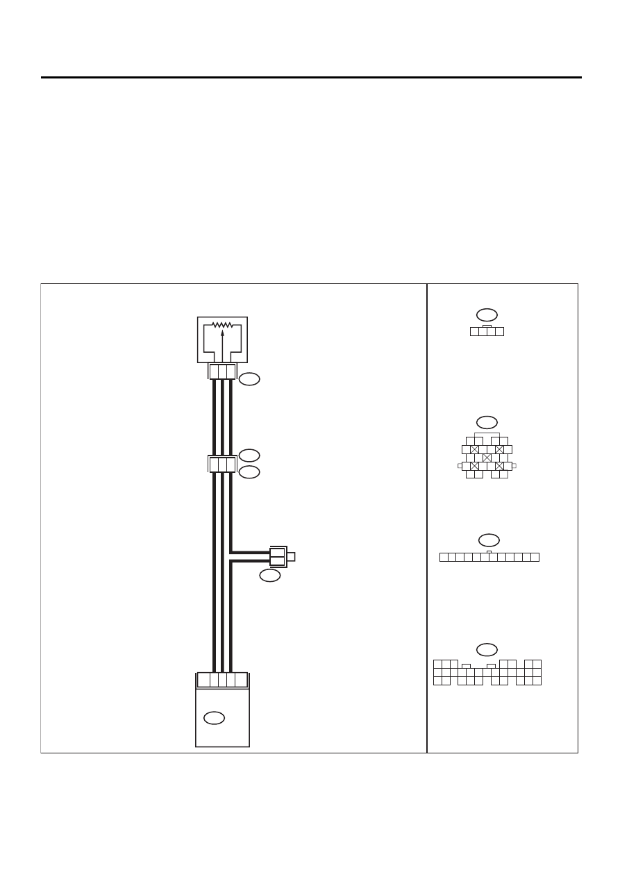
H: DTC 31 THROTTLE POSITION SENSOR
• DIAGNOSIS:
• The throttle position sensor signal is abnormal.
• The throttle position sensor is installed abnormally.
• The harness connector between ECM and throttle position sensor is in short or open.
• TROUBLE SYMPTOM:
• Erroneous idling
• Engine stalls
• Poor driving performance
CAUTION:
After repair or replacement of faulty parts, conduct CLEAR MEMORY and INSPECTION MODES. <Ref.
to EN(H4SOw/oOBD)-28, OPERATION, Clear Memory Mode.> and <Ref. to EN(H4SOw/oOBD)-26, OP-
ERATION, Inspection Mode.>
• WIRING DIAGRAM:
EN-01056
16
17
15
9
11
12
B136
2
3
4
B21
E2
E13
THROTTLE
POSITION
SENSOR
E13
B83
1 2 3 4
6
4
B83
5
4
6 7
8
2
1
9
3
10
22
23
11 12 13 14 15
24 25
26 27
16 17 18
28 29
19 20
21
30
B21
B136
ECM
1 2
5
6 7
8
13
14 15
16
9 10
11 12
3 4
17 18
19 20
1 2 3 4 5 6 7 8 9 10 11 12

EN(H4SOw/oOBD)-80
ENGINE (DIAGNOSTICS)
DIAGNOSTIC PROCEDURE WITH DIAGNOSTIC TROUBLE CODE (DTC)
Step
Value
Yes
No
1
CHECK CONDITION OF THROTTLE POSI-
TION SENSOR INSTALLATION.
Are the throttle position sensor installing screw
tightened securely?
Installing screw is securely
tightened.
Adjust throttle
position sensor
and tighten throt-
tle position sensor
installing screws
securely.
2
CHECK HARNESS BETWEEN ECM AND
THROTTLE POSITION SENSOR.
1) Disconnect connector from ECM and throt-
tle position sensor.
2) Measure resistance between ECM and
throttle position sensor.
Connector & terminal
(B136) No. 16 — (E13) No. 2:
(B136) No. 17 — (E13) No. 3:
(B136) No. 15 — (E13) No. 4:
Is the measured value less than the speci-
fied value?
1
Ω
Repair open circuit
between ECM and
throttle position
sensor.
3
CHECK HARNESS BETWEEN ECM AND
THROTTLE POSITION SENSOR CONNEC-
TOR.
1) Disconnect connector from TCM. (AT vehi-
cle)
2) Measure resistance between ECM and
chassis ground.
Connector & terminal
(B136) No. 16 — Chassis ground:
(B136) No. 17 — Chassis ground:
(B136) No. 15 — Chassis ground:
Does the measured value exceed the spec-
ified value?
1 M
Ω
Repair ground
short circuit
between ECM and
chassis ground.
4
CHECK INPUT SIGNAL FOR ECM.
1) Connect connector to ECM and throttle
position sensor.
2) Ignition switch to ON.
3) Measure voltage between ECM terminals
while throttle valve is fully closed.
Connector & terminal
(B136) No. 17 — No. 15:
Is the measured value less than the speci-
fied value?
0.1 V
5
CHECK INPUT SIGNAL FROM ECM.
Measure voltage between ECM terminals
while throttle valve is fully opened.
Connector & terminal
(B136) No. 17 — No. 15:
Does the measured value exceed the specified
value?
4.5 V
Replace ECM.
6
CHECK POOR CONTACT.
Check poor contact in throttle position sensor
connector.
Is there poor contact in throttle position sensor
connector?
There is poor contact.
Repair poor con-
tact in throttle posi-
tion sensor
connector.
Replace throttle
position sensor.
EN(H4SOw/oOBD)-81
ENGINE (DIAGNOSTICS)
DIAGNOSTIC PROCEDURE WITH DIAGNOSTIC TROUBLE CODE (DTC)
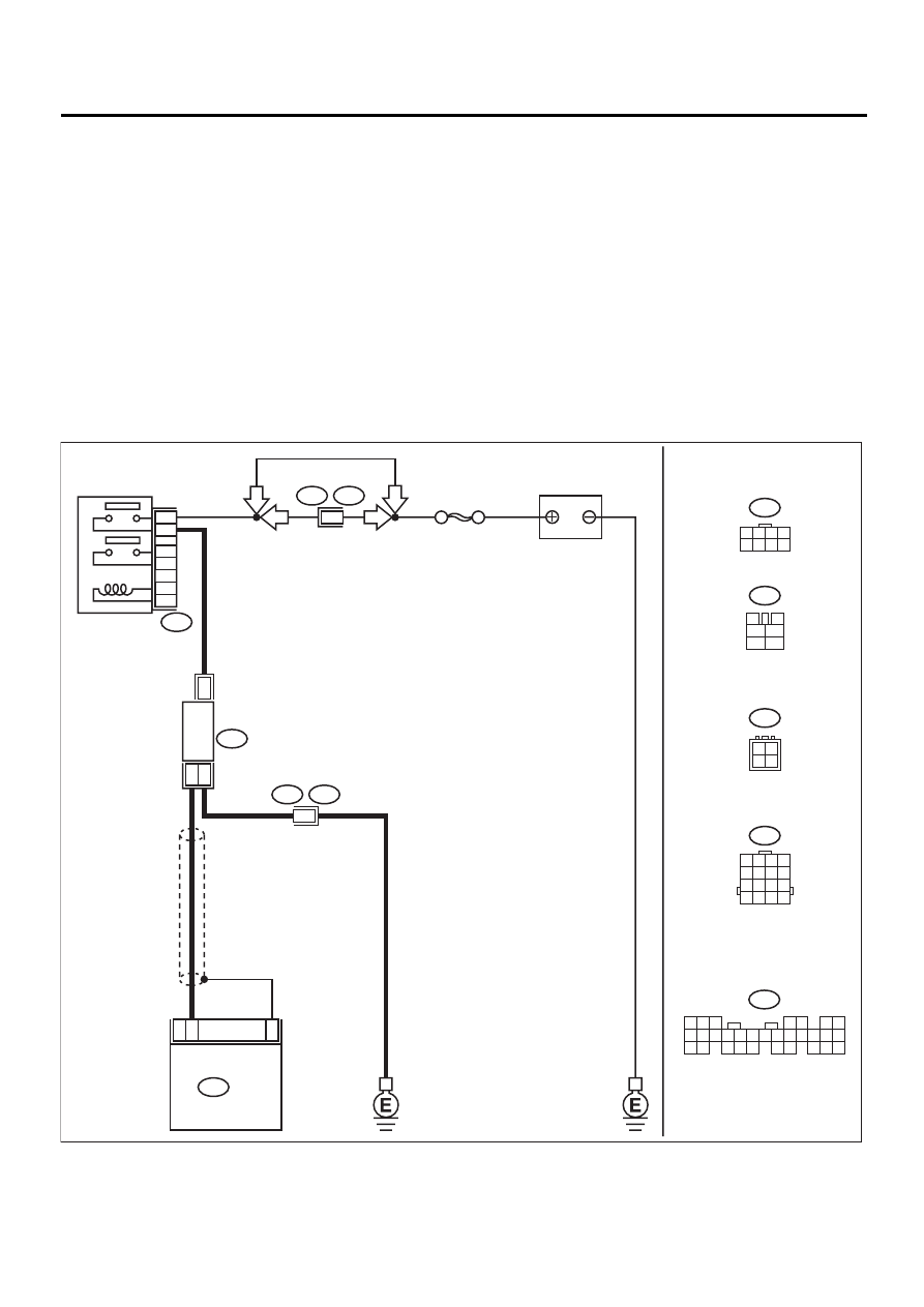
I:
DTC 32 OXYGEN SENSOR
• DIAGNOSIS:
• The oxygen sensor is not in function.
• The harness connector between ECM and oxygen sensor is in short or open.
• TROUBLE SYMPTOM:
• Failure of engine to start
• Erroneous idling
• Poor driving performance
• Engine stalls.
• Idle mixture is out of specifications.
CAUTION:
After repair or replacement of faulty parts, conduct CLEAR MEMORY and INSPECTION MODES. <Ref.
to EN(H4SOw/oOBD)-28, OPERATION, Clear Memory Mode.> and <Ref. to EN(H4SOw/oOBD)-26, OP-
ERATION, Inspection Mode.>
• WIRING DIAGRAM:
EN-01057
F44
B61
E3
B22
B47
B47
3
4
1
2
5
6
B136
B22
1 2 3 4
5 6 7 8
9 10 11 12
13 14 15 16
B18
F44
SBF-5
BATTERY
MAIN RELAY
1
2
3
5
4
6
6
LHD
LHD
RHD
RHD
1 2 3 4
5 6 7 8
23
7
ECM
OXYGEN SENSOR
2
4
1
B18
B136
15
1
2
3
4
5
4
6 7
8
2
1
9
3
10
22
23
11 12 13 14 15
24 25
26 27
16 17 18
28 29
19 20
21
30
Нет комментариевНе стесняйтесь поделиться с нами вашим ценным мнением.
Текст