Subaru Legacy III (2000-2003 year). Service manual — part 225
EN(H4SOw/oOBD)-90
ENGINE (DIAGNOSTICS)
DIAGNOSTIC PROCEDURE WITH DIAGNOSTIC TROUBLE CODE (DTC)
Step
Value
Yes
No
1
CHECK HARNESS BETWEEN ECM AND
TCM CONNECTOR.
1) Disconnect connectors from ECM and
TCM.
2) Measure resistance of harness between
ECM and chassis ground.
Connector & terminal
(B135) No. 17 — Chassis ground:
Is the measured value less than the speci-
fied value?
10
Ω
Repair ground
short circuit in har-
ness between
ECM and TCM
connector.
2
CHECK HARNESS BETWEEN ECM AND
TCM CONNECTOR.
Measure resistance of harness between ECM
and chassis ground.
Connector & terminal
(B135) No. 16 — Chassis ground:
Is the measured value less than the specified
value?
10
Ω
Repair ground
short circuit in har-
ness between
ECM and TCM
connector.
Replace TCM.
<Ref. to AT-76,
Transmission Con-
trol Module
(TCM).>
EN(H4SOw/oOBD)-91
ENGINE (DIAGNOSTICS)
DIAGNOSTIC PROCEDURE WITH DIAGNOSTIC TROUBLE CODE (DTC)
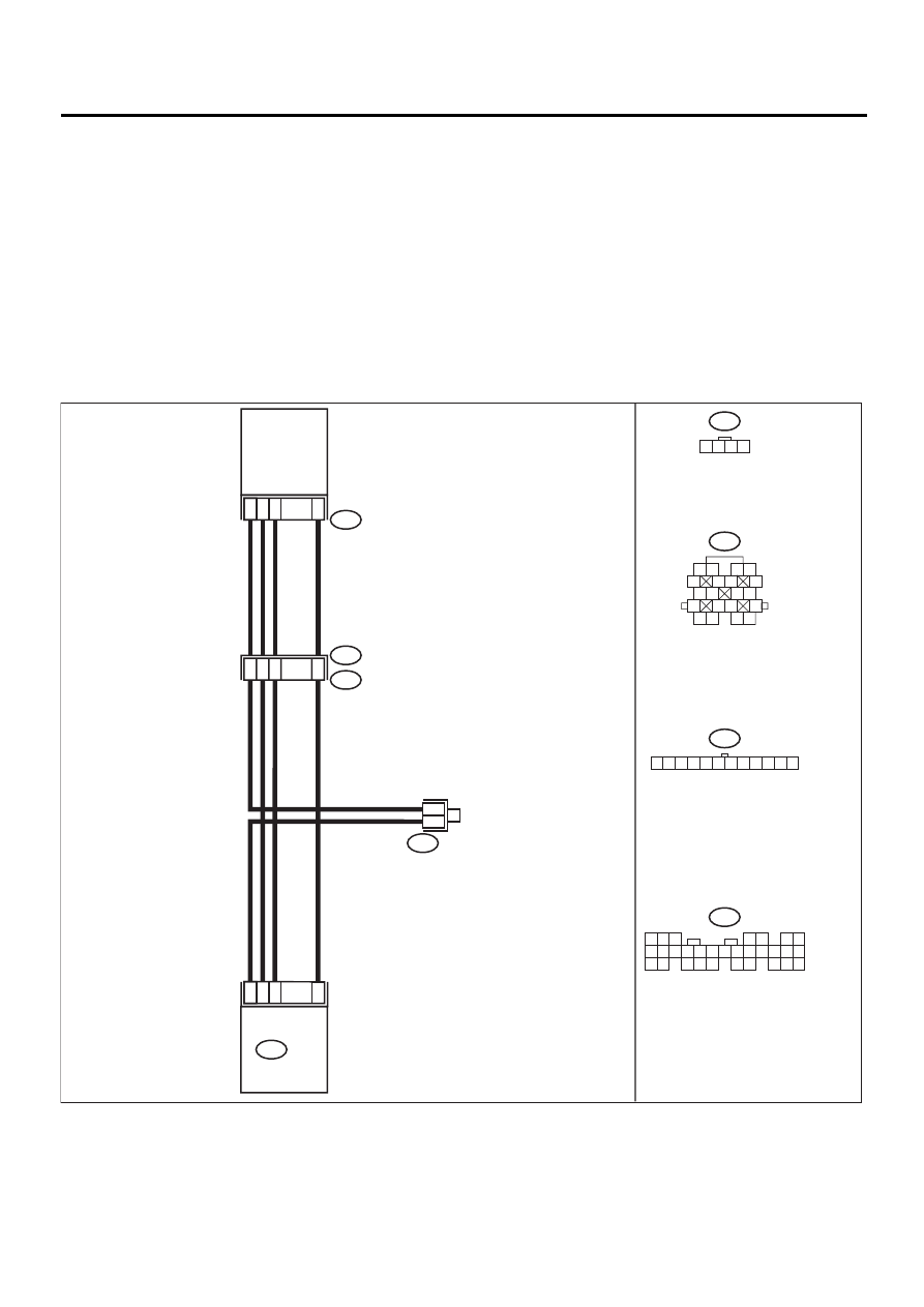
M: DTC 45 PRESSURE SENSOR
• DIAGNOSIS:
• The pressure sensor signal is abnormal.
• The harness connector between ECM and pressure sensor is in short or open.
• TROUBLE SYMPTOM:
• Erroneous idling
• Engine stalls.
• Poor driving performance
CAUTION:
After repair or replacement of faulty parts, conduct CLEAR MEMORY and INSPECTION MODES. <Ref.
to EN(H4SOw/oOBD)-28, OPERATION, Clear Memory Mode.> and <Ref. to EN(H4SOw/oOBD)-26, OP-
ERATION, Inspection Mode.>
• WIRING DIAGRAM:
EN-01055
16
15
13
5
INTAKE AIR
TEMPERATURE
AND
PRESSURE
SENSOR
4
6
5
4
6 7
8
2
1
9
3
10
22
23
11 12 13 14 15
24 25
26 27
16 17 18
28 29
19 20
21
30
B136
B83
9
15
14
12
B21
E2
1
4
2
3
E21
B83
E20
1 2 3 4
ECM
B21
1 2
5
6 7
8
13
14 15
16
9 10
11 12
3 4
17 18
19 20
1 2 3 4 5 6 7 8 9 10 11 12
B136

EN(H4SOw/oOBD)-92
ENGINE (DIAGNOSTICS)
DIAGNOSTIC PROCEDURE WITH DIAGNOSTIC TROUBLE CODE (DTC)
Step
Value
Yes
No
1
CHECK HARNESS BETWEEN ECM AND
PRESSURE SENSOR CONNECTOR.
1) Disconnect connector from pressure sen-
sor.
2) Turn ignition switch to ON.
3) Measure voltage between pressure sensor
connector and engine ground.
Connector & terminal
(E20) No. 3 (+) — Engine ground (–):
Is the measured value within the specified
value?
4.5 — 5.5 V
Repair open or
ground short cir-
cuit in harness
between ECM and
pressure sensor.
2
CHECK HARNESS BETWEEN ECM AND
PRESSURE SENSOR CONNECTOR.
1) Disconnect connector from ECM.
2) Measure resistance of harness between
ECM and pressure sensor connector.
Connector & terminal
(B136) No. 16 — (E20) No. 1:
(B136) No. 5 — (E20) No. 4:
Is the measured value less than the speci-
fied value?
1
Ω
Repair open circuit
in harness
between ECM and
pressure sensor
connector.
3
CHECK HARNESS BETWEEN ECM AND
PRESSURE SENSOR CONNECTOR.
Measure resistance of harness between ECM
connector and chassis ground.
Connector & terminal
(B136) No. 5 — Chassis ground:
(B136) No. 16 — Chassis ground:
Does the measured value exceed the specified
value?
1 M
Ω
Repair ground
short circuit in har-
ness between
ECM and pressure
sensor connector.
4
CHECK INPUT SIGNAL FOR ECM.
1) Turn ignition switch to OFF.
2) Connect connector to ECM and pressure
sensor.
3) Turn ignition switch to ON.
4) Measure voltage between ECM and chas-
sis ground.
Connector & terminal
(B136) No. 5 (+) — Chassis ground (–):
Is the measured value within the specified
value?
2.3 — 2.5 V
Replace pressure
sensor. <Ref. to
FU(H4SOw/
oOBD)-32, Intake
Air Temperature
and Pressure Sen-
sor.>
5
CHECK INPUT SIGNAL FOR ECM.
1) Start engine, and idle it.
2) Measure voltage between ECM and chas-
sis ground.
Connector & terminal
(B136) No. 5 (+) — Chassis ground (–):
Is the measured value within the specified
value?
1.2 — 1.8 V
Replace pressure
sensor. <Ref. to
FU(H4SOw/
oOBD)-32, Intake
Air Temperature
and Pressure Sen-
sor.>
6
CHECK POOR CONTACT.
Check poor contact in pressure sensor con-
nector.
Is there poor contact in pressure sensor con-
nector?
There is poor contact.
Repair poor con-
tact in pressure
sensor connector.
Replace pressure
sensor. <Ref. to
FU(H4SOw/
oOBD)-32, Intake
Air Temperature
and Pressure Sen-
sor.>
EN(H4SOw/oOBD)-93
ENGINE (DIAGNOSTICS)
DIAGNOSTIC PROCEDURE WITH DIAGNOSTIC TROUBLE CODE (DTC)
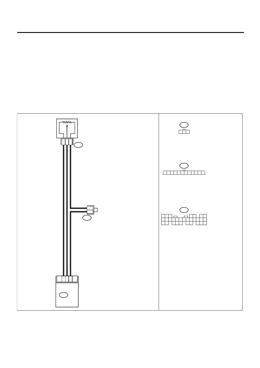
N: DTC 46 CO RESISTOR (GENERAL SPEC. VEHICLES)
• DIAGNOSIS:
• The CO resistor signal is abnormal.
• The harness connector between ECM and CO resistor is in short or open.
• The CO value is not adjusted to specifications.
• TROUBLE SYMPTOM:
• Erroneous idling
• Mixture ratio is too rich or too lean.
CAUTION:
After repair or replacement of faulty parts, conduct CLEAR MEMORY and INSPECTION MODES. <Ref.
to EN(H4SOw/oOBD)-28, OPERATION, Clear Memory Mode.> and <Ref. to EN(H4SOw/oOBD)-26, OP-
ERATION, Inspection Mode.>
• WIRING DIAGRAM:
EN-01061
16
12
15
B136
3
2
1
B155
CO RESISTOR
B83
6
5
B83
5
4
6 7
8
2
1
9
3
10
22
23
11 12 13 14 15
24 25
26 27
16 17 18
28 29
19 20
21
30
B136
ECM
1 2 3 4 5 6 7 8 9 10 11 12
B155
1 2 3
Нет комментариевНе стесняйтесь поделиться с нами вашим ценным мнением.
Текст