Subaru Legacy III (2000-2003 year). Service manual — part 437
CO(H4DOSTC)-2
COOLING
GENERAL DESCRIPTION
1. General Description
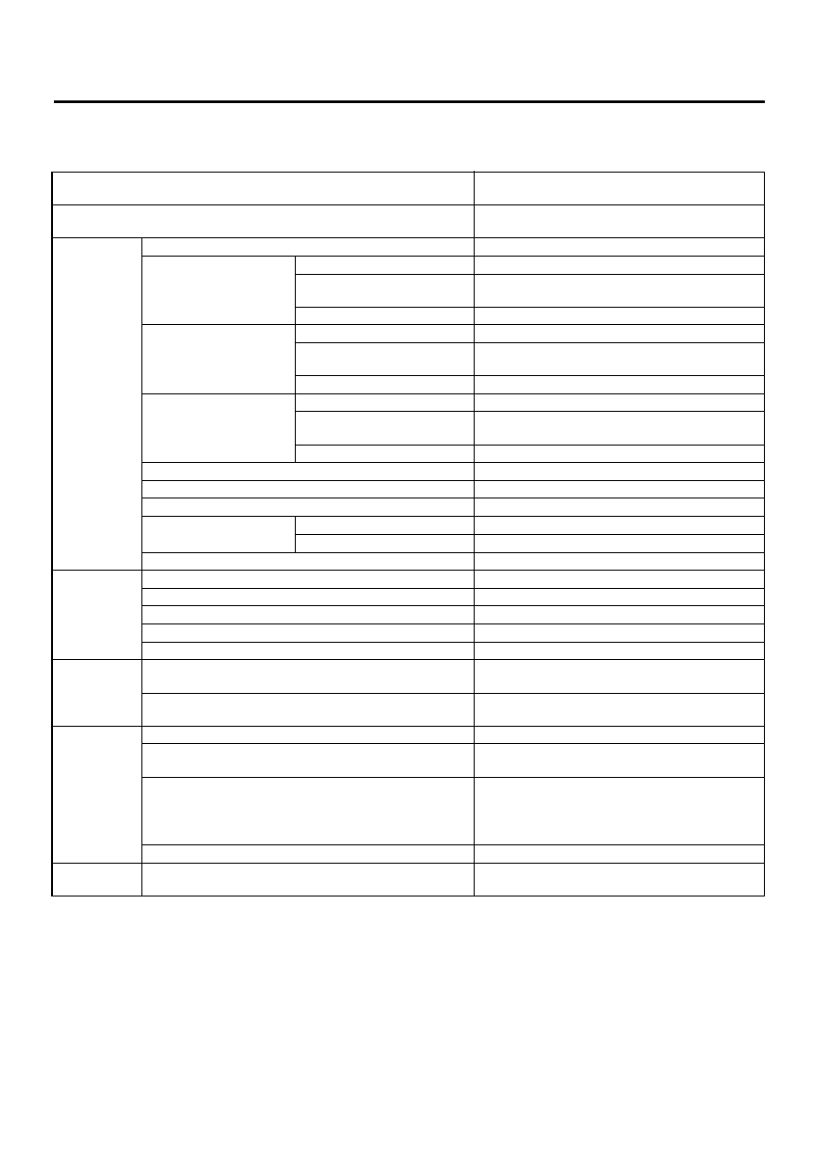
A: SPECIFICATIONS
Cooling system
Electric fan + Forced engine coolant circulation sys-
tem
Total engine coolant capacity
2
(US qt, Imp qt)
MT: Approx. 7.7 (8.1, 6.8)
AT: Approx. 7.6 (8.0, 6.7)
Water pump
Type
Centrifugal impeller type
Discharge performance I
Discharge
20
2
(5.3 US gal, 4.4 Imp gal)/min.
Pump speed—Discharge pres-
sure (pressure leak)
760 rpm — 2.9 kPa [0.3 mAq (1.0 ftAq)]
Engine coolant temperature
85
°
C (185
°
F)
Discharge performance II
Discharge
100
2
(26.4 US gal, 22.0 Imp gal)/min.
Pump speed—Discharge pres-
sure (pressure leak)
3,000 rpm — 49.0 kPa [5.0 mAq (16.4 ftAq)]
Engine coolant temperature
85
°
C (185
°
F)
Discharge performance III
Discharge
200
2
(52.8 US gal, 44.0 Imp gal)/min.
Pump speed—Discharge pres-
sure (pressure leak)
6,000 rpm — 225.4 kPa [23.0 mAq (75.5 ftAq)]
Engine coolant temperature
85
°
C (185
°
F)
Impeller diameter
76 mm (2.99 in)
Number of impeller vanes
8
Pump pulley diameter
60 mm (2.36 in)
Clearance between impel-
ler and case
Standard
0.5 — 0.7 mm (0.020 — 0.028 in)
Limit
1.0 mm (0.039 in)
“Thrust” runout of impeller end
0.5 mm (0.020 in)
Thermostat
Type
Wax pellet type
Starts to open
76 — 80
°
C (169 — 176
°
F)
Fully opened
91
°
C (196
°
F)
Valve lift
9.0 mm (0.354 in) or more
Valve bore
35 mm (1.38 in)
Radiator fan
Motor
75 W (main fan)
75 W (sub fan)
Fan diameter
×
Blade
300 mm (11.81 in)
×
5 (main fan)
300 mm (11.81 in)
×
4 (sub fan)
Radiator
Type
Down flow, pressure type
Core dimensions
691.5
×
340
×
16 mm
(27.22
×
13.39
×
0.63 in)
Pressure range in which cap valve is open or closed
Above: 108
±
15 kPa
(1.1
±
0.15 kg/cm
2
, 16
±
2 psi)
Below:
−
1.0 to
−
4.9 kPa
(
−
0.01 to
−
0.05 kg/cm
2
,
−
0.1 to
−
0.7 psi)
Fins
Corrugated fin type
Reservoir
tank
Capacity
0.5
2
(0.5 US qt, 0.4 Imp qt)
CO(H4DOSTC)-3
COOLING
GENERAL DESCRIPTION
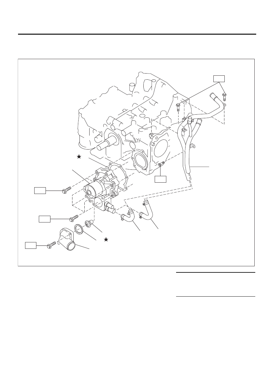
B: COMPONENT
1. WATER PUMP
(1) Thermostat case
(5) Gasket
Tightening torque: N·m (kgf-m, ft-lb)
(2) Gasket
(6) Heater by-pass hose
T1: First 12 (1.2, 8.7)
Second 12 (1.2, 8.7)
(3) Thermostat
(7) Coolant filler tank by-pass hose
(4) Water pump ASSY
(8) Water by-pass hose
T2: 6.5 (0.66, 4.8)
( 1 )
( 2 )
( 3 )
( 4 )
( 5 )
( 6 )
( 7 )
T2
( 8 )
T2
T2
T1
T1
CO-00201
CO(H4DOSTC)-4
COOLING
GENERAL DESCRIPTION
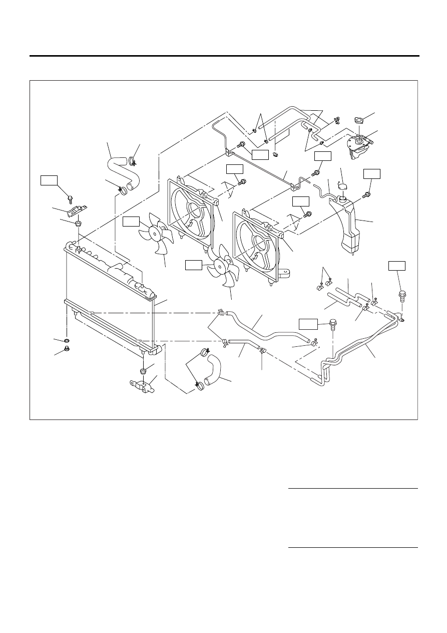
2. RADIATOR AND RADIATOR FAN
(1) Radiator lower cushion
(14) Radiator main fan and main fan
motor ASSY
(25) ATF outlet hose B (AT vehicles
only)
(2) Radiator
(3) Radiator upper cushion
(15) Radiator outlet hose
(26) ATF inlet hose B (AT vehicles
only)
(4) Radiator upper bracket
(16) Radiator drain plug
(5) Clamp
(17) Engine coolant filler tank
(27) ATF pipe (AT vehicles only)
(6) Radiator inlet hose
(18) Engine coolant filler tank cap
(7) Engine coolant reservoir tank cap
(19) Engine coolant hose
Tightening torque: N·m (kgf-m, ft-lb)
(8) Overflow hose
(20) Radiator lower bracket
T1: 3.4 (0.35, 2.5)
(9) Engine coolant reservoir tank
(21) O-ring
T2: 4.4 (0.45, 3.3)
(10) Overflow pipe
(22) ATF hose clamp (AT vehicles
only)
T3: 4.9 (0.50, 3.6)
(11) Sub fan shroud
T4: 18 (1.8, 13.0)
(12) Radiator sub fan and sub fan
motor ASSY
(23) ATF outlet hose A (AT vehicles
only)
T5: 12 (1.2, 8.7)
(13) Main fan shroud
(24) ATF inlet hose A (AT vehicles
only)
CO-00145
T3
(7)
(18)
(17)
(5)
(5)
(19)
(9)
T3
T3
T5
T2
T2
T1
(13)
(11)
(14)
(5)
(5)
(6)
(8)
T4
(5)
(15)
(1)
(2)
(20)
(16)
(3)
(4)
(10 )
(21)
(12)
T1
(24)
(25)
(22)
(22)
(22)
(22)
(22)
(22)
T5
(26)
(27)
(23)
CO(H4DOSTC)-5
COOLING
GENERAL DESCRIPTION
C: CAUTION
• Wear working clothing, including a cap, protec-
tive goggles, and protective shoes during opera-
tion.
• Remove contamination including dirt and corro-
sion before removal, installation or disassembly.
• Keep the disassembled parts in order and pro-
tect them from dust or dirt.
• Before removal, installation or disassembly, be
sure to clarify the failure. Avoid unnecessary re-
moval, installation, disassembly, and replacement.
• Be careful not to burn your hands, because each
part in the vehicle is hot after running.
• Be sure to tighten fasteners including bolts and
nuts to the specified torque.
• Place shop jacks or safety stands at the specified
points.
• Before disconnecting electrical connectors of
sensors or units, be sure to disconnect ground ca-
ble from battery.
Нет комментариевНе стесняйтесь поделиться с нами вашим ценным мнением.
Текст