Subaru Legacy III (2000-2003 year). Service manual — part 438
CO(H4DOSTC)-6
COOLING
GENERAL DESCRIPTION
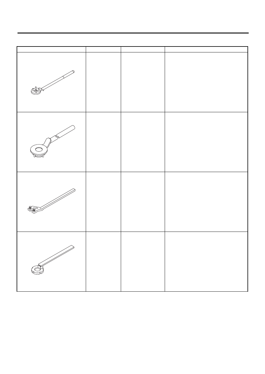
D: PREPARATION TOOL
ILLUSTRATION
TOOL NUMBER
DESCRIPTION
REMARKS
499977100 (MT
model)
CRANK PULLEY
WRENCH
Used for fixing crankshaft pulley when loos-
ening and tightening crankshaft pulley bolts.
499977400 (AT
model)
CRANK PULLEY
WRENCH
Used for fixing crankshaft pulley when loos-
ening and tightening crankshaft pulley bolts.
18231AA010
CAMSHAFT
SPROCKET
WRENCH
• Used for removing and installing camshaft
sprocket. (Intake side)
• Camshaft sprocket wrench (499207100) is
also available.
499207400
CAMSHAFT
SPROCKET
WRENCH
Used for removing and installing camshaft
sprocket. (Exhaust side)
ST-499977100
ST-499977400
ST18231AA010
ST-499207400
CO(H4DOSTC)-7
COOLING
RADIATOR MAIN FAN SYSTEM
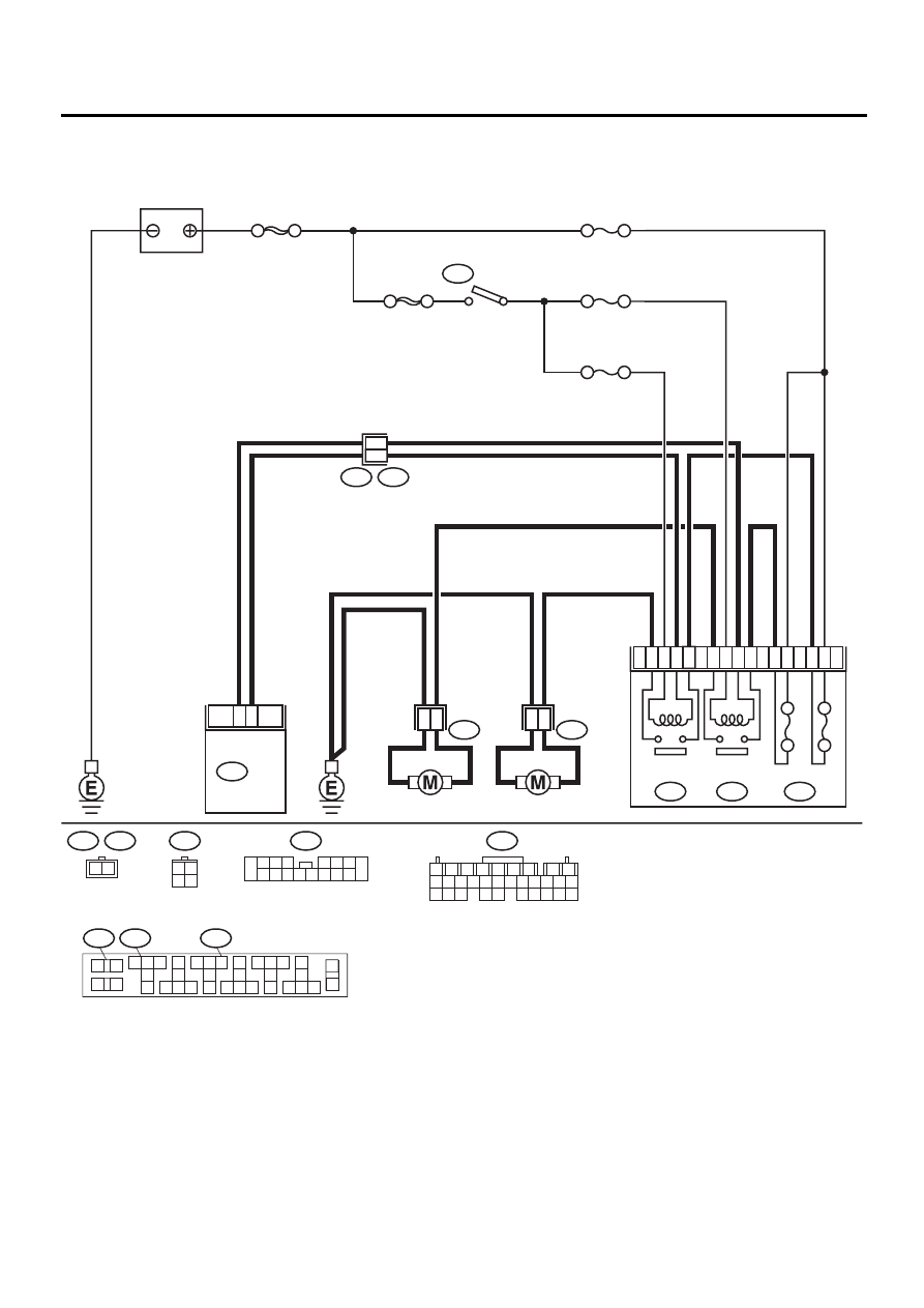
2. Radiator Main Fan System
A: SCHEMATIC
CO-00146
2
1
4
3
21
22
24
20
8
7
5
9
20A
20A
SUB FAN
RELAY
AIR CONDITIONING RELAY HOLDER
SUB FAN
MOTOR
MAIN FAN
MOTOR
MAIN FAN
RELAY
F28
F16
F66
F27
1
2
F17
B100
F2
B72
1
2
8
9
NO. 3
NO. 18
NO. 17
SBF-4
SBF-1
IGNITION
SWITCH
B72
3 4
1 2
B137
BATTERY
17
28
B137
ECM
F16
F17
2 1
F27
1
2
3
4
5 6 7
8
9
11
10
13
12
14
21
20
23
22
24
31
30
33
32
34
16
15
17
18
19
26
25
27
28
29
35
36
F66
F28
F2
1
2 3 4
5 6 7
9 10 11 12 13 14 15 16
8
1
2
7
8
9
5
6
3
4
10
11
12
19
20
21
29
30
31
13
14
15
16
17
27
28
18
22
23
24
25
26

CO(H4DOSTC)-8
COOLING
RADIATOR MAIN FAN SYSTEM
B: INSPECTION
DETECTING CONDITION:
Condition:
• Engine coolant temperature is above 95
°
C (203
°
F).
• Vehicle speed is below 19 km/h (12 MPH).
TROUBLE SYMPTOM:
• Radiator main fan does not rotate under the above conditions.
Step
Value
Yes
No
1
CHECK POWER SUPPLY TO MAIN FAN MO-
TOR.
CAUTION:
Be careful not to overheat engine during re-
pair.
1) Turn ignition switch to OFF.
2) Disconnect connector from main fan motor.
3) Start the engine, and warm it up until
engine coolant temperature increases over
95
°
C (203
°
F).
4) Stop the engine and turn ignition switch to
ON.
5) Measure voltage between main fan motor
connector and chassis ground.
Connector & terminal
(F17) No. 2 (+) — Chassis ground (
−−−−
):
Does the measured value exceed the spec-
ified value?
10 V
2
CHECK GROUND CIRCUIT OF MAIN FAN
MOTOR.
1) Turn ignition switch to OFF.
2) Measure resistance between main fan
motor connector and chassis ground.
Connector & terminal
(F17) No. 1 — Chassis ground:
Is the measured value less than the speci-
fied valve?
5
Ω
Repair open circuit
in harness
between main fan
motor connector
and chassis
ground.
3
CHECK POOR CONTACT.
Check poor contact in main fan motor connec-
tor.
Is there poor contact in main fan motor con-
nector?
There is poor contact.
Repair poor con-
tact in main fan
motor connector.
4
CHECK MAIN FAN MOTOR.
Connect battery positive (+) terminal to termi-
nal No. 2, and negative (
−
) terminal to terminal
No. 1 of main fan motor connector.
Does the main fan rotate?
The main fan rotates.
Repair poor con-
tact in main fan
motor connector.
Replace main fan
motor with a new
one.
5
CHECK POWER SUPPLY TO MAIN FAN RE-
LAY.
1) Turn ignition switch to OFF.
2) Remove main fan relay from A/C relay
holder.
3) Measure voltage between main fan relay
terminal and chassis ground.
Connector & terminal
(F66) No. 8 (+) — Chassis ground (
−−−−
):
Does the measured value exceed the spec-
ified value?
10 V

CO(H4DOSTC)-9
COOLING
RADIATOR MAIN FAN SYSTEM
6
CHECK POWER SUPPLY TO MAIN FAN RE-
LAY.
1) Turn ignition switch to ON.
2) Measure voltage between main fan relay
terminal and chassis ground.
Connector & terminal
(F66) No. 5 (+) — Chassis ground (
−−−−
):
Does the measured value exceed the spec-
ified value?
10 V
7
CHECK 20 A FUSE.
1) Remove 20 A fuse from A/C relay holder.
2) Check condition of fuse.
Is the fuse blown-out?
Fuse is blown-out.
Replace fuse.
8
CHECK POWER SUPPLY TO A/C RELAY
HOLDER 20 A FUSE TERMINAL.
Measure voltage of harness between A/C relay
holder 20 A fuse terminal and chassis ground.
Connector & terminal
(F27) No. 1 (+) — Chassis ground (
−−−−
):
Does the measured value exceed the specified
value?
10 V
Repair open circuit
in harness
between 20 A fuse
and main fan relay
terminal.
Repair open circuit
in harness
between main fuse
box connector and
20 A fuse terminal.
9
CHECK FUSE.
1) Turn ignition switch to OFF.
2) Remove fuse No. 18 from joint box.
3) Check fuse.
Is the fuse blown-out?
Fuse is blown-out.
Replace fuse.
Repair open circuit
in harness
between main fan
relay and ignition
switch.
10
CHECK MAIN FAN RELAY.
1) Turn ignition switch to OFF.
2) Measure resistance of main fan relay.
Terminal
No. 8 — No. 9:
Does the measured value exceed the spec-
ified value?
1 M
Ω
Replace main fan
relay.
11
CHECK MAIN FAN RELAY.
1) Connect battery to terminals No. 5 and No.
7 of main fan relay.
2) Measure resistance of main fan relay.
Terminal
No. 8 — No. 9:
Is the measured value less than the speci-
fied valve?
1
Ω
Replace main fan
relay.
12
CHECK HARNESS BETWEEN MAIN FAN
RELAY TERMINAL AND MAIN FAN MOTOR
CONNECTOR.
Measure resistance of harness between main
fan motor connector and main fan relay termi-
nal.
Connector & terminal
(F17) No. 2 — (F66) No. 9:
Is the measured value less than the specified
valve?
1
Ω
Repair open circuit
in harness
between main fan
motor connector
and main fan relay
terminal.
Step
Value
Yes
No
Нет комментариевНе стесняйтесь поделиться с нами вашим ценным мнением.
Текст