Subaru Legacy III (2000-2003 year). Service manual — part 883
AC-68
HVAC SYSTEM (AUTO A/C) (DIAGNOSTICS)
DIAGNOSTIC PROCEDURE WITH DIAGNOSTIC TROUBLE CODE (DTC) (RHD
MODEL)
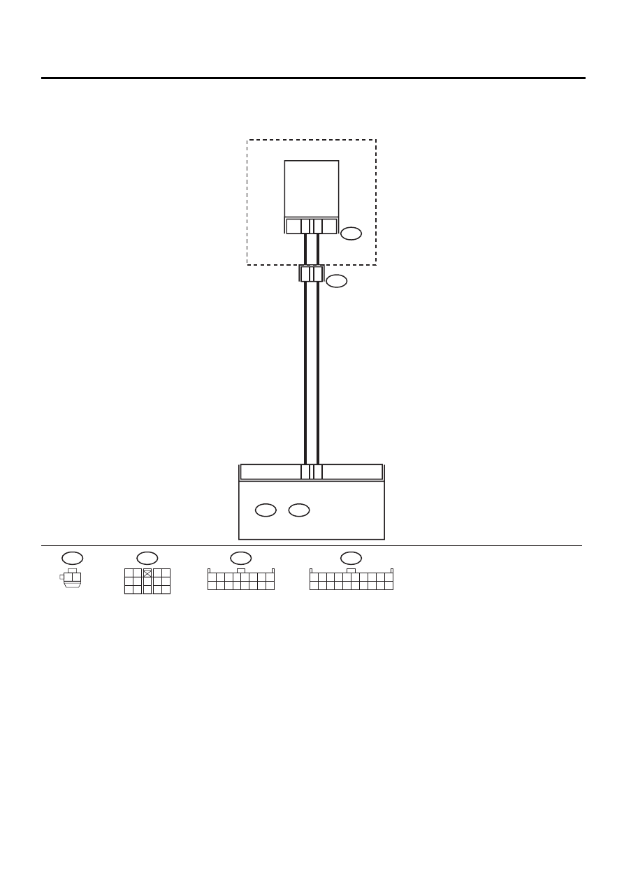
C: DTC 23 OR –23 (EVAPORATOR SENSOR)
WIRING DIAGRAM:
AC-00374
A12
A10
A
i52
2
1
EVAPORATION
THRMO SWITCH
BLOWER MODULE
9
10
i49
B:
i48
A:
AUTO A/C
CONTROL MODULE
A
i52
1 2
3 4
5 6
7
8 9
10 11 12 13 14
i49
1 2 3 4 5 6 7 8 9 10
11 12 13 14 15 16 17 18 19 20
i48
B:
A:
1 2 3 4 5 6 7 8
9 10 11 12 13 14 15 16
1 2

AC-69
HVAC SYSTEM (AUTO A/C) (DIAGNOSTICS)
DIAGNOSTIC PROCEDURE WITH DIAGNOSTIC TROUBLE CODE (DTC) (RHD
MODEL)
Step
Value
Yes
No
1
CHECK EVAPORATOR SENSOR.
1) Turn ignition switch to OFF.
2) Remove glove box.
3) Disconnect connector from evaporator sen-
sor.
4) Measure resistance between connector ter-
minals of evaporator sensor.
Terminals
No. 1 — No. 2:
Is the measured value within the specified
value?
Approx. 1.8 to 2.0 k
Ω
at 20
°
C
(68
°
F)
Replace evapora-
tor sensor.
2
CHECK INPUT SIGNAL FOR EVAPORATOR
SENSOR.
1) Turn ignition switch to ON.
2) Measure signal voltage between connector
terminal of evaporator sensor and chassis
ground.
Connector & terminal
(A) No. 2 (+) — Chassis ground (
−−−−
):
Is the measured value same as the speci-
fied value?
Approx. 3.3 V
3
CHECK OUTPUT SIGNAL FROM A/C CON-
TROL MODULE.
1) Turn ignition switch to OFF.
2) Pull out A/C control module.
3) Turn ignition switch to ON.
4) Measure voltage between A/C control mod-
ule connector terminals.
Connector & terminal
(i48) No. 12 (+) — No. 10 (-):
Is the measured value same as the speci-
fied value?
Approx. 3.3 V
4
CHECK HARNESS CONNECTOR BETWEEN
A/C CONTROL MODULE AND EVAPORA-
TOR SENSOR.
1) Turn ignition switch to OFF.
2) Disconnect connectors from A/C control
module.
3) Measure resistance of harness between A/
C control module and evaporator sensor.
Connector & terminal
(i48) No. 12 — (A) No. 2:
Is the measured value less than the speci-
fied value?
1
Ω
Repair harness
between A/C con-
trol module and
evaporator sensor.
5
CHECK HARNESS CONNECTOR BETWEEN
A/C CONTROL MODULE AND EVAPORA-
TOR SENSOR.
Measure resistance of harness between A/C
control module and evaporator sensor.
Connector & terminal
(i48) No. 10 — (A) No. 1:
Is the measured value less than the specified
value?
1
Ω
Repair harness
between A/C con-
trol module and
evaporator sensor.
6
CHECK POOR CONTACT.
Check poor contact in A/C control module con-
nector.
Is there poor contact in connector?
There is no poor contact.
Replace A/C con-
trol module.
Repair connector.
AC-70
HVAC SYSTEM (AUTO A/C) (DIAGNOSTICS)
DIAGNOSTIC PROCEDURE WITH DIAGNOSTIC TROUBLE CODE (DTC) (RHD
MODEL)
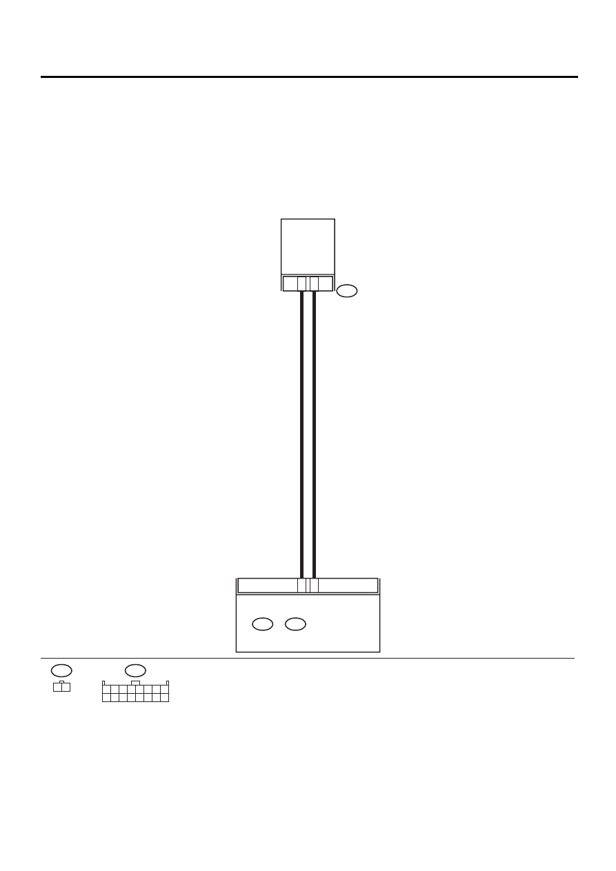
D: DTC 25 OR –25 (SUNLOAD SENSOR)
TROUBLE SYMPTOM:
• Sensor identified that sunlight is at maximum. Then, A/C system is controlled to COOL side.
• Sensor identified that sunlight is at minimum. Then, A/C system is controlled to HOT side.
NOTE:
When the sunload sensor is checked inside the passenger compartment or in the shade, DTC “25” may ap-
pear on the indicator. Always check the sunload sensor in a place where it senses direct sunlight.
WIRING DIAGRAM:
AC-00375
A4
A5
i51
2
1
SUNLOAD
SENSOR
i51
1 2
i48
A:
i49
B:
i48
A:
AUTO A/C
CONTROL MODULE
1 2 3 4 5 6 7 8
9 10 11 12 13 14 15 16

AC-71
HVAC SYSTEM (AUTO A/C) (DIAGNOSTICS)
DIAGNOSTIC PROCEDURE WITH DIAGNOSTIC TROUBLE CODE (DTC) (RHD
MODEL)
Step
Value
Yes
No
1
CHECK SUNLOAD SENSOR.
1) Turn ignition switch to OFF.
2) Remove sunload sensor. <Ref. to AC-48,
REMOVAL, Sunload Sensor (Auto A/C).>
3) Turn ignition switch ON.
4) Measure sunload sensor input voltage.
Connector & terminal
(i51) No. 2 (+) — No. 1 (-):
Is the measured value same as the speci-
fied value?
Approx. 4.2 V
2
CHECK HARNESS CONNECTOR BETWEEN
A/C CONTROL MODULE AND SUNLOAD
SENSOR.
1) Turn ignition switch to OFF.
2) Disconnect connectors from A/C control
module.
3) Measure resistance of harness between A/
C control module and sunload sensor.
Connector & terminal
(i51) No. 1 — (i48) No. 5:
Is the measured value less than the speci-
fied value?
1
Ω
Repair harness
between A/C con-
trol module and
sunload sensor.
3
CHECK HARNESS CONNECTOR BETWEEN
A/C CONTROL MODULE AND SUNLOAD
SENSOR.
Measure resistance of harness between A/C
control module and sunload sensor.
Connector & terminal
(i51) No. 2 — (i48) No. 4:
Is the measured value less than the specified
value?
1
Ω
Repair harness
between A/C con-
trol module and
sunload sensor.
4
Check A/C control module input voltage.
1) Connect A/C control module and sunload
sensor connector.
2) Turn ignition switch ON.
3) Measure voltage between A/C control mod-
ule connector terminals.
Connector & terminal
(i48) No. 4 (+) — No. 5 (
−−−−
):
Is the measured value same as the speci-
fied value?
Approx. 2.5 V
Replace sunload
sensor.
5
CHECK POOR CONTACT.
Check poor contact in A/C control module con-
nector.
Is there poor contact in connector?
There is no poor contact.
Replace A/C con-
trol module.
Repair connector.
Нет комментариевНе стесняйтесь поделиться с нами вашим ценным мнением.
Текст