Subaru Legacy III (2000-2003 year). Service manual — part 882
AC-64
HVAC SYSTEM (AUTO A/C) (DIAGNOSTICS)
DIAGNOSTIC PROCEDURE WITH DIAGNOSTIC TROUBLE CODE (DTC) (LHD
MODEL)
MEMO:
AC-65
HVAC SYSTEM (AUTO A/C) (DIAGNOSTICS)
DIAGNOSTIC PROCEDURE WITH DIAGNOSTIC TROUBLE CODE (DTC) (RHD
MODEL)
11.Diagnostic Procedure with Diagnostic Trouble Code (DTC) (RHD
Model)
A: DTC 21 OR –21 (IN-VEHICLE SENSOR)
TROUBLE SYMPTOM:
When turning AUTO switch to ON, blower fan speed, outlet port and inlet port is not changed.
NOTE:
If DTC 21 or –21 appears on the display, replace the A/C control module. The in-vehicle sensor is built into
the A/C control module and cannot be replaced as a single unit.
AC-66
HVAC SYSTEM (AUTO A/C) (DIAGNOSTICS)
DIAGNOSTIC PROCEDURE WITH DIAGNOSTIC TROUBLE CODE (DTC) (RHD
MODEL)
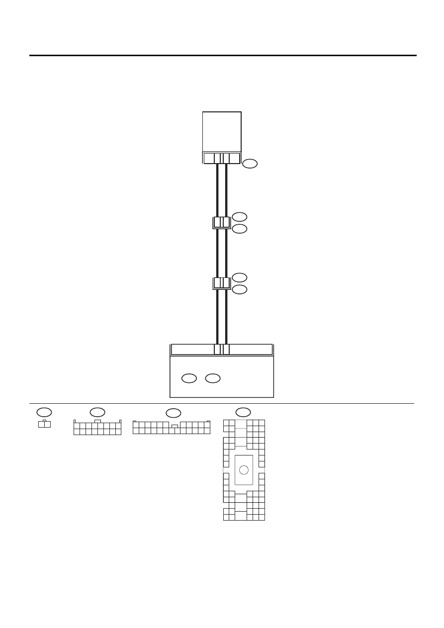
B: DTC 22 OR –22 (AMBIENT SENSOR)
TROUBLE SYMPTOM:
Fan speed, outlets and inlets are not switched when AUTO or ECON switch is ON.
WIRING DIAGRAM:
AC-00373
A11
A10
F78
F2
B100
B36
i1
1
2
AMBIENT
SENSOR
4
3
D6
E6
F78
1 2
i48
A:
B36
B4 B5 B6
A4 A5 A6
C5 C6
F6
D4 D5 D6
F1
H1
C4
G6
G1
C2
K1
M1 M2
K6
L1
D1 D2
A1 A2
B1 B2
I6
J6
L2
I1
J1
H6
M4 M5 M6
L4 L5 L6
N5 N6
O4 O5 O6
N4
P4 P5
N2
O1 O2
P1 P2
N3
O3
P3
P6
A3
B3
C3
E4 E5 E6
E1 E2
i49
B:
i48
A:
AUTO A/C
CONTROL MODULE
1 2 3 4 5 6 7 8
9 10 11 12 13 14 15 16
F2
1
12
9
8
7
6
17
5
4
3
2
14
13
15 16
18
21
20
19
22 23 24
11
10

AC-67
HVAC SYSTEM (AUTO A/C) (DIAGNOSTICS)
DIAGNOSTIC PROCEDURE WITH DIAGNOSTIC TROUBLE CODE (DTC) (RHD
MODEL)
Step
Value
Yes
No
1
CHECK AMBIENT SENSOR.
1) Turn ignition switch to OFF.
2) Disconnect connector from ambient sensor.
3) Measure resistance connector terminals of
ambient sensor.
Terminals
No. 1 — No. 2:
Is the measured value same as the speci-
fied value?
Approx. 1.7 k
Ω
at 25
°
C (77
°
Replace ambient
sensor.
2
CHECK INPUT SIGNAL FOR AMBIENT SEN-
SOR.
1) Turn ignition ON.
2) Measure voltage between ambient sensor
harness connector terminals.
Connector & terminal
(F78) No. 2 (+) — No. 1 (-):
Is the measured value same as the speci-
fied value?
Approx. 4.5 V
3
CHECK OUTPUT SIGNAL FROM A/C CON-
TROL MODULE.
1) Turn ignition switch to OFF.
2) Pull out A/C control panel.
3) Disconnect connector from ambient sensor.
4) Turn ignition switch to ON.
5) Measure voltage between connector termi-
nals of A/C control module.
Connector & terminal
(i48) No. 11 (+) — No. 10 (-):
Is the measured value same as the speci-
fied value?
Approx. 4.5 V
4
CHECK HARNESS CONNECTOR BETWEEN
A/C CONTROL MODULE AND AMBIENT
SENSOR.
1) Turn ignition switch to OFF.
2) Disconnect connectors from A/C control
module.
3) Measure resistance of harness between A/
C control module and ambient sensor.
Connector & terminal
(F78) No. 1 — (i48) No. 10:
Is the measured value less than the speci-
fied value?
1
Ω
Repair harness
between A/C con-
trol module and
ambient sensor.
5
CHECK HARNESS CONNECTOR BETWEEN
A/C CONTROL MODULE AND AMBIENT
SENSOR.
Measure resistance of harness between A/C
control module and ambient sensor.
Connector & terminal
(F78) No. 2 — (i48) No. 11:
Is the measured value less than the specified
value?
1
Ω
Repair harness
between A/C con-
trol module and
ambient sensor.
6
CHECK POOR CONTACT.
Check poor contact in A/C control module con-
nector.
Is there poor contact in connector?
There is no poor contact.
Replace A/C con-
trol module.
Repair connector.
Нет комментариевНе стесняйтесь поделиться с нами вашим ценным мнением.
Текст