Subaru Legacy III (2000-2003 year). Service manual — part 884
AC-72
HVAC SYSTEM (AUTO A/C) (DIAGNOSTICS)
DIAGNOSTIC PROCEDURE WITH DIAGNOSTIC TROUBLE CODE (DTC) (RHD
MODEL)
E: DTC 26 OR 27 (AIR MIX MOTOR POTENTIOMETER LINE)
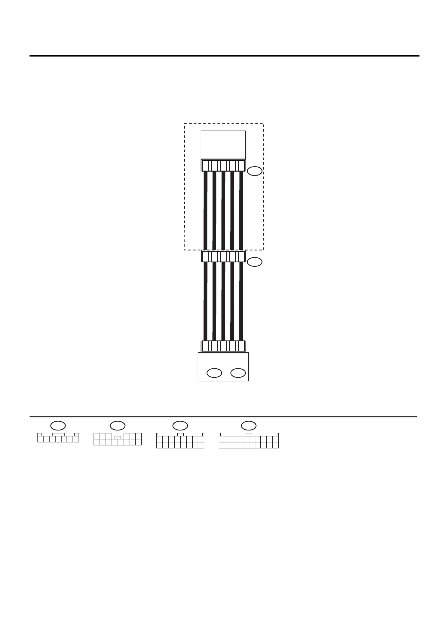
WIRING DIAGRAM:
AC-00376
1
3
5
6
7
D
i45
AIR MIX
DOOR ACTUATOR
9
11
10
8
7
A10
A5
A6
B1
B11
HEATER MODULE
AUTO A/C
CONTROL MODULE
A: i48
B: i49
D
3 2 1 4 5 6 7
i49
1 2 3 4 5 6 7 8 9 10
11 12 13 14 15 16 17 18 19 20
i48
1 2 3 4 5 6 7 8
9 10 11 12 13 14 15 16
A:
B:
i45
1 2 3
4 5 6
7 8 9 10 11 12 13 14
AC-73
HVAC SYSTEM (AUTO A/C) (DIAGNOSTICS)
DIAGNOSTIC PROCEDURE WITH DIAGNOSTIC TROUBLE CODE (DTC) (RHD
MODEL)
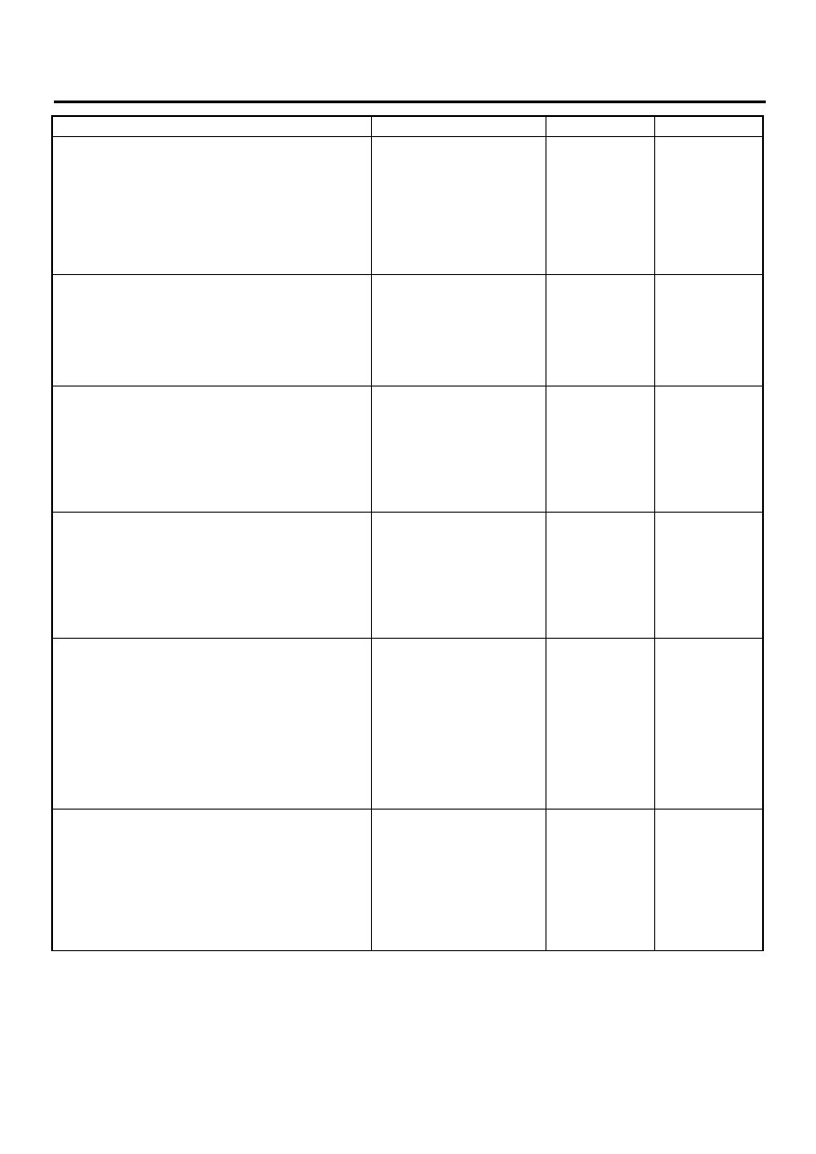
Step
Value
Yes
No
1
CHECK AIR MIX DOOR ACTUATOR.
1) Turn ignition switch to OFF.
2) Remove air mix door actuator.
3) Make sure that air mix door actuator is
operated when connecting battery positive
(+) terminal to terminal No. 6, battery nega-
tive (-) terminal to terminal No. 7 of air mix
door actuator.
Does the air mix door actuator operate?
Air mix door actuator operates. Go to step 2.
Replace air mix
door actuator.
2
CHECK POTENTIOMETER.
Measure resistance for the power supply line
of the potentiometer.
Terminals
(D) No. 1 — No. 3:
Is the measured value same as the specified
value?
Approx. 6.0 k
Ω
Replace air mix
door actuator.
3
CHECK POTENTIOMETER.
Measure resistance for the signal line of the
potentiometer, when the lever is in the FULL
COOL position.
Terminals
(D) No. 1 — No. 5:
Is the measured value same as the specified
value?
Approx. 1.2 k
Ω
Replace air mix
door actuator.
4
CHECK POTENTIOMETER.
Measure resistance for the signal line of the
potentiometer, when the lever is in the FULL
HOT position.
Terminals
(D) No. 1 — No. 5:
Is the measured value same as the specified
value?
Approx. 4.5 k
Ω
Replace air mix
door actuator.
5
CHECK HARNESS CONNECTOR BETWEEN
A/C CONTROL MODULE AND AIR MIX
DOOR ACTUATOR.
1) Disconnect connector from A/C control
module.
2) Measure resistance of harness between A/
C control module and air mix door actuator.
Connector & terminal
(i48) No. 6 — (D) No. 5:
Is the measured value less than the speci-
fied value?
1
Ω
Repair harness
between A/C con-
trol module and air
mix door actuator.
6
CHECK HARNESS CONNECTOR BETWEEN
A/C CONTROL MODULE AND AIR MIX
DOOR ACTUATOR.
Measure resistance of harness between A/C
control module and air mix door actuator.
Connector & terminal
(i48) No. 5 — (D) No. 3:
Is the measured value less than the specified
value?
1
Ω
Repair harness
between A/C con-
trol module and air
mix door actuator.

AC-74
HVAC SYSTEM (AUTO A/C) (DIAGNOSTICS)
DIAGNOSTIC PROCEDURE WITH DIAGNOSTIC TROUBLE CODE (DTC) (RHD
MODEL)
7
CHECK HARNESS CONNECTOR BETWEEN
A/C CONTROL MODULE AND AIR MIX
DOOR ACTUATOR.
Measure resistance of harness between A/C
control module and air mix door actuator.
Connector & terminal
(i48) No. 10 — (D) No. 1:
Is the measured value less than the specified
value?
1
Ω
Repair harness
between A/C con-
trol module and air
mix door actuator.
8
CHECK HARNESS CONNECTOR BETWEEN
A/C CONTROL MODULE AND AIR MIX
DOOR ACTUATOR.
Measure resistance of harness between A/C
control module and air mix door actuator.
Connector & terminal
(i49) No. 1 — (D) No. 6:
Is the measured value less than the specified
value?
1
Ω
Repair harness
between A/C con-
trol module and air
mix door actuator.
9
CHECK HARNESS CONNECTOR BETWEEN
A/C CONTROL MODULE AND AIR MIX
DOOR ACTUATOR.
Measure resistance of harness between A/C
control module and air mix door actuator.
Connector & terminal
(i49) No. 11 — (D) No. 7:
Is the measured value less than the specified
value?
1
Ω
Repair harness
between A/C con-
trol module and air
mix door actuator.
10
CHECK POOR CONTACT.
Check poor contact in A/C control module.
Is there poor connection in connector?
There is no poor connection.
Replace A/C con-
trol module.
Replace connec-
tor.
Step
Value
Yes
No
AC-75
HVAC SYSTEM (AUTO A/C) (DIAGNOSTICS)
DIAGNOSTIC PROCEDURE WITH DIAGNOSTIC TROUBLE CODE (DTC) (RHD
MODEL)
MEMO:
Нет комментариевНе стесняйтесь поделиться с нами вашим ценным мнением.
Текст