Subaru Legacy III (2000-2003 year). Service manual — part 730
ABS-138
ABS (DIAGNOSTICS)
DIAGNOSTICS CHART WITH SUBARU SELECT MONITOR
AF:DTC 56 BATTERY SHORT IN G SENSOR CIRCUIT
DIAGNOSIS:
• Faulty G sensor output voltage
TROUBLE SYMPTOM:
• ABS does not operate.
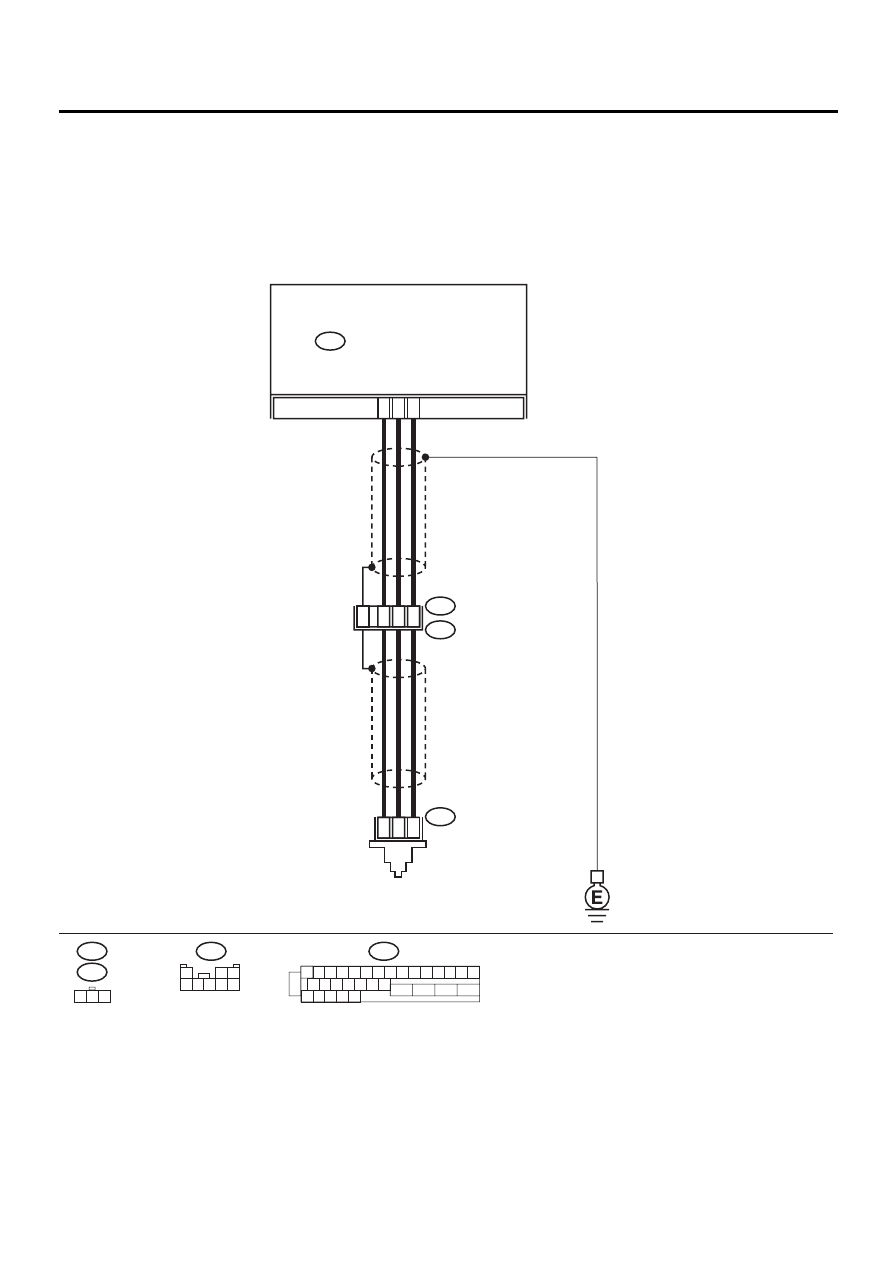
WIRING DIAGRAM:
ABS00312
F55
R70
F62
ABS CONTROL MODULE AND
HYDRAULIC CONTROL UNIT
ABS
G SENSOR
F49
2
1
3
F49
1 2 3 4 5 6 7 8 9 10 11 12 13 14 15
16 17 18 19 20 21 22
27 28 29 30 31
23
24
25
26
3
7
6
28
1
2
3
F55
R49
R70
2
8
30
1
2 3
4 5 6 7 8

ABS-139
ABS (DIAGNOSTICS)
DIAGNOSTICS CHART WITH SUBARU SELECT MONITOR
Step
Value
Yes
No
1
CHECK OUTPUT OF G SENSOR USING SE-
LECT MONITOR.
1) Select “Current data display & Save” on the
select monitor.
2) Read the G sensor output in select monitor
data display.
Is the G sensor output on the monitor dis-
play between within the specified range
when the G sensor is in horizontal position?
2.1 - 2.5 V
2
CHECK POOR CONTACT IN CONNECTORS.
Is there poor contact in connector between
ABSCM&H/U and G sensor?
There is no poor contact.
Repair connector.
3
CHECK ABSCM&H/U.
1) Connect all connectors.
2) Erase the memory.
3) Perform inspection mode.
4) Read out the DTC.
Is the same DTC still being output?
Same DTC is not indicated.
Replace
ABSCM&H/U.
<Ref. to ABS-6,
ABS Control Mod-
ule and Hydraulic
Control Unit
(ABSCM&H/U).>
4
CHECK ANY OTHER DTC APPEARANCE.
Are other DTC being output?
Other DTC is not indicated.
A temporary poor
contact.
Proceed with the
diagnosis corre-
sponding to the
DTC.
5
CHECK FREEZE FRAME DATA.
1) Select “Freeze frame data” on the select
monitor.
2) Read front right wheel speed on the select
monitor display.
Is the front right wheel speed on monitor
display same as the specified value?
0 km/h (0 MPH)
6
CHECK FREEZE FRAME DATA.
Read front left wheel speed on the select mon-
itor display.
Is the front left wheel speed on monitor display
same as the specified value?
0 km/h (0 MPH)
7
CHECK FREEZE FRAME DATA.
Read rear right wheel speed on the select
monitor display.
Is the rear right wheel speed on monitor dis-
play same as the specified value?
0 km/h (0 MPH)
8
CHECK FREEZE FRAME DATA.
Read rear left wheel speed on the select moni-
tor display.
Is the rear left wheel speed on monitor display
same as the specified value?
0 km/h (0 MPH)
9
CHECK FREEZE FRAME DATA.
Read G sensor output on the select monitor
display.
Does measured value exceed the specified
value on monitor display?
3.65 V

ABS-140
ABS (DIAGNOSTICS)
DIAGNOSTICS CHART WITH SUBARU SELECT MONITOR
10
CHECK OPEN CIRCUIT IN G SENSOR OUT-
PUT HARNESS AND GROUND HARNESS.
1) Turn ignition switch to OFF.
2) Disconnect connector from ABSCM&H/U.
3) Measure resistance between ABSCM&H/U
connector terminals.
Connector & terminal
(F49) No. 6 — No. 28:
Is the measured value within the specified
range?
5.0 - 5.6 k
Ω
Repair harness/
connector
between G sensor
and ABSCM&H/U.
11
CHECK BATTERY SHORT OF HARNESS.
1) Turn ignition switch to OFF.
2) Remove console box.
3) Disconnect connector from G sensor.
4) Disconnect connector from ABSCM&H/U.
5) Measure voltage between ABSCM&H/U
connector and chassis ground.
Connector & terminal
(F49) No. 6 (+) — Chassis ground (
−−−−
):
Is the measured value less than the speci-
fied value?
1 V
Repair harness
between G sensor
and ABSCM&H/U.
12
CHECK BATTERY SHORT OF HARNESS.
1) Turn ignition switch to ON.
2) Measure voltage between ABSCM&H/U
connector and chassis ground.
Connector & terminal
(F49) No. 6 (+) — Chassis ground (
−−−−
):
Is the measured value less than the speci-
fied value?
1 V
Repair harness
between G sensor
and ABSCM&H/U.
13
CHECK POOR CONTACT IN CONNECTORS.
Is there poor contact in connector between
ABSCM&H/U and G sensor?
There is no poor contact.
Repair connector.
14
CHECK ABSCM&H/U.
1) Connect all connectors.
2) Erase the memory.
3) Perform inspection mode.
4) Read out the DTC.
Is the same DTC still being output?
Same DTC is not indicated.
Replace
ABSCM&H/U.
<Ref. to ABS-6,
ABS Control Mod-
ule and Hydraulic
Control Unit
(ABSCM&H/U).>
15
CHECK ANY OTHER DTC APPEARANCE.
Are other DTC being output?
Other DTC is not indicated.
A temporary poor
contact.
Proceed with the
diagnosis corre-
sponding to the
DTC.
16
CHECK INPUT VOLTAGE OF G SENSOR.
1) Turn ignition switch to OFF.
2) Remove console box.
3) Disconnect G sensor from body. (Do not
disconnect connector.)
4) Turn ignition switch to ON.
5) Measure voltage between G sensor con-
nector terminals.
Connector & terminal
(R70) No. 1 (+) — No. 3 (
−−−−
):
Is the measured value within the specified
range?
4.75 - 5.25 V
Repair harness/
connector
between G sensor
and ABSCM&H/U.
Step
Value
Yes
No

ABS-141
ABS (DIAGNOSTICS)
DIAGNOSTICS CHART WITH SUBARU SELECT MONITOR
17
CHECK OPEN CIRCUIT IN G SENSOR OUT-
PUT HARNESS AND GROUND HARNESS.
1) Turn ignition switch to OFF.
2) Disconnect connector from ABSCM&H/U.
3) Measure resistance between ABSCM&H/U
connector terminals.
Connector & terminal
(F49) No. 6 — No. 28:
Is the measured value within the specified
range?
5.0 - 5.6 k
Ω
Repair harness/
connector
between G sensor
and ABSCM&H/U.
18
CHECK G SENSOR.
1) Connect connector to G sensor.
2) Connect connector to ABSCM&H/U.
3) Turn ignition switch to ON.
4) Measure voltage between G sensor con-
nector terminals.
Connector & terminal
(R70) No. 2 (+) — No. 3 (
−−−−
):
Is the voltage within th especified range
when G sensor is horizontal?
2.1 - 2.5 V
Replace G sen-
sor. <Ref. to ABS-
21, G Sensor.>
19
CHECK G SENSOR.
Measure voltage between G sensor connector
terminals.
Connector & terminal
(R70) No. 2 (+) — No. 3 (
−−−−
):
Is the voltage within the specified range when
G sensor is inclined forwards to 90
°
?
3.7 - 4.1 V
Replace G sen-
sor. <Ref. to ABS-
21, G Sensor.>
20
CHECK G SENSOR.
Measure voltage between G sensor connector
terminals.
Connector & terminal
(R70) No. 2 (+) — No. 3 (
−−−−
):
Is the voltage within the specifed range when
G sensor is inclined backwards to 90
°
?
0.5 - 0.9 V
Replace G sen-
sor. <Ref. to ABS-
21, G Sensor.>
21
CHECK POOR CONTACT IN CONNECTORS.
Turn ignition switch to OFF.
Is there poor contact in connector between
ABSCM&H/U and G sensor?
There is no poor contact.
Repair connector.
22
CHECK ABSCM&H/U.
1) Connect all connectors.
2) Erase the memory.
3) Perform inspection mode.
4) Read out the DTC.
Is the same DTC still being output?
Same DTC is not indicated.
Replace
ABSCM&H/U.
<Ref. to ABS-6,
ABS Control Mod-
ule and Hydraulic
Control Unit
(ABSCM&H/U).>
23
CHECK ANY OTHER DTC APPEARANCE.
Are other DTC being output?
Other DTC is not indicated.
A temporary poor
contact.
Proceed with the
diagnosis corre-
sponding to the
DTC.
Step
Value
Yes
No
Нет комментариевНе стесняйтесь поделиться с нами вашим ценным мнением.
Текст