Subaru Legacy III (2000-2003 year). Service manual — part 729
ABS-134
ABS (DIAGNOSTICS)
DIAGNOSTICS CHART WITH SUBARU SELECT MONITOR
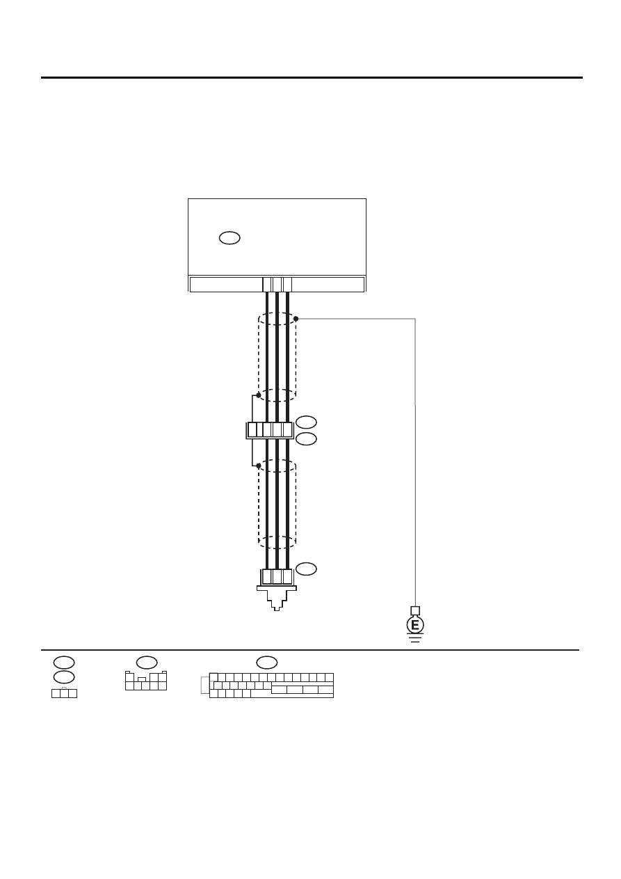
AE:DTC 56 OPEN OR SHORT CIRCUIT IN G SENSOR CIRCUIT
DIAGNOSIS:
• Faulty G sensor output voltage
TROUBLE SYMPTOM:
• ABS does not operate.
WIRING DIAGRAM:
ABS00312
F55
R70
F62
ABS CONTROL MODULE AND
HYDRAULIC CONTROL UNIT
ABS
G SENSOR
F49
2
1
3
F49
1 2 3 4 5 6 7 8 9 10 11 12 13 14 15
16 17 18 19 20 21 22
27 28 29 30 31
23
24
25
26
3
7
6
28
1
2
3
F55
R49
R70
2
8
30
1
2 3
4 5 6 7 8

ABS-135
ABS (DIAGNOSTICS)
DIAGNOSTICS CHART WITH SUBARU SELECT MONITOR
Step
Value
Yes
No
1
CHECK OUTPUT OF G SENSOR USING SE-
LECT MONITOR.
1) Select “Current data display & Save” on the
select monitor.
2) Read the G sensor output in select monitor
data display.
Is the G sensor output on the monitor dis-
play within the specified range when the G
sensor is in horizontal position?
2.1 - 2.5 V
2
CHECK POOR CONTACT IN CONNECTORS.
Is there poor contact in connector between
ABSCM&H/U and G sensor?
There is no poor contact.
Repair connector.
3
CHECK ABSCM&H/U.
1) Connect all connectors.
2) Erase the memory.
3) Perform inspection mode.
4) Read out the DTC.
Is the same DTC still being output?
Same DTC is not indicated.
Replace
ABSCM&H/U.
<Ref. to ABS-6,
ABS Control Mod-
ule and Hydraulic
Control Unit
(ABSCM&H/U).>
4
CHECK ANY OTHER DTC APPEARANCE.
Are other DTC being output?
Other DTC is not indicated.
A temporary poor
contact.
Proceed with the
diagnosis corre-
sponding to the
DTC.
5
CHECK INPUT VOLTAGE OF G SENSOR.
1) Turn ignition switch to OFF.
2) Remove console box.
3) Disconnect G sensor from body. (Do not
disconnect connector.)
4) Turn ignition switch to ON.
5) Measure voltage between G sensor con-
nector terminals.
Connector & terminal
(R70) No. 1 (+) — No. 3 (
−−−−
):
Is the measured value within the specified
range?
4.75 - 5.25 V
Repair harness/
connector
between G sensor
and ABSCM&H/U.
6
CHECK OPEN CIRCUIT IN G SENSOR OUT-
PUT HARNESS AND GROUND HARNESS.
1) Turn ignition switch to OFF.
2) Disconnect connector from ABSCM&H/U.
3) Measure resistance between ABSCM&H/U
connector terminals.
Connector & terminal
(F49) No. 6 — No. 28:
Is the measured value within the specified
range?
5.0 - 5.6 k
Ω
Repair harness/
connector
between G sensor
and ABSCM&H/U.
7
CHECK GROUND SHORT IN G SENSOR
OUTPUT HARNESS.
1) Disconnect connector from G sensor.
2) Measure resistance between ABSCM&H/U
connector and chassis ground.
Connector & terminal
(F49) No. 6 — Chassis ground:
Does the measured value exceed the spec-
ified value?
1 M
Ω
Repair harness
between G sensor
and ABSCM&H/U.
ABS-136
ABS (DIAGNOSTICS)
DIAGNOSTICS CHART WITH SUBARU SELECT MONITOR
8
CHECK G SENSOR.
1) Connect connector to G sensor.
2) Connect connector to ABSCM&H/U.
3) Turn ignition switch to ON.
4) Measure voltage between G sensor con-
nector terminals.
Connector & terminal
(R70) No. 2 (+) — No. 3 (
−−−−
):
Is the voltage between within the specified
range when G sensor is horizontal?
2.1 - 2.5 V
Replace G sen-
sor. <Ref. to ABS-
21, G Sensor.>
9
CHECK G SENSOR.
Measure voltage between G sensor connector
terminals.
Connector & terminal
(R70) No. 2 (+) — No. 3 (
−−−−
):
Is the voltage between within the specified
range when G sensor is inclined forwards to
90
°
?
3.7 - 4.1 V
Replace G sen-
sor. <Ref. to ABS-
21, G Sensor.>
10
CHECK G SENSOR.
Measure voltage between G sensor connector
terminals.
Connector & terminal
(R70) No. 2 (+) — No. 3 (
−−−−
):
Is the voltage between within the specified
range when G sensor is inclined backwards to
90
°
?
0.5 - 0.9 V
Replace G sen-
sor. <Ref. to ABS-
21, G SENSOR, .>
11
CHECK POOR CONTACT IN CONNECTORS.
Turn ignition switch to OFF.
Is there poor contact in connector between
ABSCM&H/U and G sensor?
There is no poor contact.
Repair connector.
12
CHECK ABSCM&H/U.
1) Connect all connectors.
2) Erase the memory.
3) Perform inspection mode.
4) Read out the DTC.
Is the same DTC still being output?
Same DTC is not indicated.
Replace
ABSCM&H/U.
<Ref. to ABS-6,
ABS Control Mod-
ule and Hydraulic
Control Unit
(ABSCM&H/U).>
13
CHECK ANY OTHER DTC APPEARANCE.
Are other DTC being output?
Other DTC is not indicated.
A temporary poor
contact.
Proceed with the
diagnosis corre-
sponding to the
DTC.
Step
Value
Yes
No
ABS-137
ABS (DIAGNOSTICS)
DIAGNOSTICS CHART WITH SUBARU SELECT MONITOR
MEMO:
Нет комментариевНе стесняйтесь поделиться с нами вашим ценным мнением.
Текст