Subaru Legacy III (2000-2003 year). Service manual — part 728
ABS-130
ABS (DIAGNOSTICS)
DIAGNOSTICS CHART WITH SUBARU SELECT MONITOR
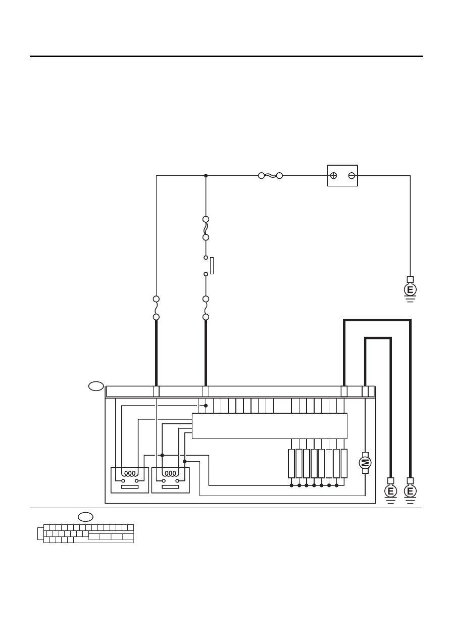
AC:DTC 52 MOTOR MALFUNCTION
DIAGNOSIS:
• Faulty motor
• Faulty motor relay
• Faulty harness connector
TROUBLE SYMPTOM:
• ABS does not operate.
WIRING DIAGRAM:
ABS00298
ABS CONTROL MODULE AND
HYDRAULIC CONTROL UNIT
1 2 3 4 5 6 7 8 9 10 11 12 13 14 15
16 17 18 19 20 21 22
27 28 29 30 31
23
24
25
26
F49
25
1
23
26
VALVE RELAY
F49
MOTOR RELAY
FR OUTLET
FR INLET
RL OUTLET
RL INLET
RR OUTLET
RR INLET
FL OUTLET
FL INLET
SOLENOID
VA
L
V
E
PUMP MO
T
O
R
SBF HOLDER 50A
NO
. 10 15A
SBF-4 50A
IGNITION
SWITCH
SBF-1 100A
BATTERY

ABS-131
ABS (DIAGNOSTICS)
DIAGNOSTICS CHART WITH SUBARU SELECT MONITOR
Step
Value
Yes
No
1
CHECK INPUT VOLTAGE OF ABSCM&H/U.
1) Turn ignition switch to OFF.
2) Disconnect connector from ABSCM&H/U.
3) Turn ignition switch to ON.
4) Measure voltage between ABSCM&H/U
connector and chassis ground.
Connector & terminal
(F49) No. 25 (+) — Chassis ground (
−−−−
):
Is the measured value within the specified
range?
10 - 15 V
Repair harness/
connector
between battery
and ABSCM&H/U
and check fuse
SBF6.
2
CHECK GROUND CIRCUIT OF MOTOR.
1) Turn ignition switch to OFF.
2) Measure resistance between ABSCM&H/U
connector and chassis ground.
Connector & terminal
(F49) No. 26 — Chassis ground:
Is the measured value less than the speci-
fied value?
0.5
Ω
Repair
ABSCM&H/U
ground harness.
3
CHECK INPUT VOLTAGE OF ABSCM&H/U.
1) Run the engine at idle.
2) Measure voltage between ABSCM&H/U
connector and chassis ground.
Connector & terminal
(F49) No. 1 (+) — Chassis ground (
−−−−
):
Is the measured value within the specified
range?
10 - 15 V
Repair harness
connector
between battery,
ignition switch and
ABSCM&H/U.
4
CHECK GROUND CIRCUIT OF ABSCM&H/U.
1) Turn ignition switch to OFF.
2) Measure resistance between ABSCM&H/U
connector and chassis ground.
Connector & terminal
(F49) No. 23 — Chassis ground:
Is the measured value less than the speci-
fied value?
0.5
Ω
Repair
ABSCM&H/U
ground harness.
5
CHECK MOTOR OPERATION.
Operate the sequence control. <Ref. to ABS-
9, ABS Sequence Control.>
NOTE:
Use the diagnosis connector to operate the se-
quence control.
Can motor revolution noise (buzz) be heard
when carrying out the sequence control?
Operating sound is produced.
Replace
ABSCM&H/U.
<Ref. to ABS-6,
ABS Control Mod-
ule and Hydraulic
Control Unit
(ABSCM&H/U).>
6
CHECK POOR CONTACT IN CONNECTORS.
Turn ignition switch to OFF.
Is there poor contact in connector between
generator, battery and ABSCM&H/U?
There is no poor contact.
Repair connector.
7
CHECK ABSCM&H/U.
1) Connect all connectors.
2) Erase the memory.
3) Perform inspection mode.
4) Read out the DTC.
Is the same DTC still being output?
Same DTC is not indicated.
Replace
ABSCM&H/U.
<Ref. to ABS-6,
ABS Control Mod-
ule and Hydraulic
Control Unit
(ABSCM&H/U).>
8
CHECK ANY OTHER DTC APPEARANCE.
Are other DTC being output?
Other DTC is not indicated.
A temporary poor
contact.
Proceed with the
diagnosis corre-
sponding to the
DTC.
ABS-132
ABS (DIAGNOSTICS)
DIAGNOSTICS CHART WITH SUBARU SELECT MONITOR
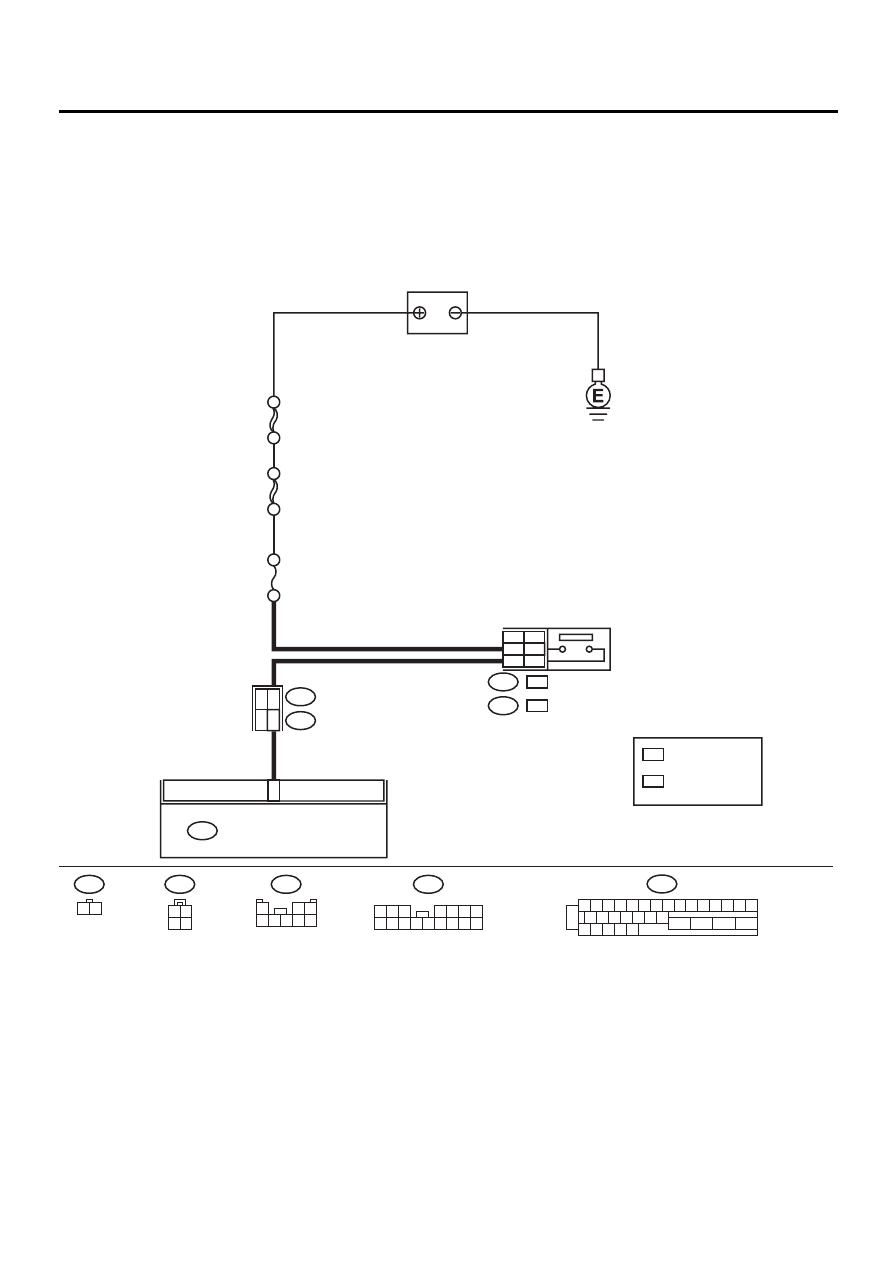
AD:DTC 54 STOP LIGHT SWITCH SIGNAL CIRCUIT MALFUNCTION
DIAGNOSIS:
• Faulty stop light switch
TROUBLE SYMPTOM:
• ABS does not operate.
WIRING DIAGRAM:
ABS00311
2
ABS CONTROL MODULE AND
HYDRAULIC CONTROL UNIT
F49
B64
1 2
1 2 3 4 5 6 7 8 9 10 11 12 13 14 15
16 17 18 19 20 21 22
27 28 29 30 31
23
24
25
26
F49
2
3
1
2
STOP LIGHT
SWITCH
B64
B65
:
:
: WITHOUT CRUISE
CONTROL
: WITH CRUISE
CONTROL
B65
1 2
3 4
B62
F45
NO
. 16 20A
BATTERY
SBF-1 100A
WC
OC
WC
OC
WC
OC
SBF-2 50A
6
7
RHD
LHD
:LHD
F45
1 2 3
4 5 6 7
8 9 10 11 12 13 14 15 16
F45
1
2 3
4 5 6 7 8

ABS-133
ABS (DIAGNOSTICS)
DIAGNOSTICS CHART WITH SUBARU SELECT MONITOR
Step
Value
Yes
No
1
CHECK OUTPUT OF STOP LIGHT SWITCH
USING SELECT MONITOR.
1) Select “Current data display & Save” on the
select monitor.
2) Release the brake pedal.
3) Read the stop light switch output in the
select monitor data display.
Is the reading indicated on monitor display
less than the specified value?
1.5 V
2
CHECK OUTPUT OF STOP LIGHT SWITCH
USING SELECT MONITOR.
1) Depress the brake pedal.
2) Read the stop light switch output in the
select monitor data display.
Is the reading indicated on monitor display
within the specified range?
10 - 15 V
3
CHECK IF STOP LIGHTS COME ON.
Depress the brake pedal.
Do stop lights turn on?
Stop lights come on.
Repair stop lights
circuit.
4
CHECK OPEN CIRCUIT IN HARNESS.
1) Turn ignition switch to OFF.
2) Disconnect connector from ABSCM&H/U.
3) Depress brake pedal.
4) Measure voltage between ABSCM&H/U
connector and chassis ground.
Connector & terminal
(F49) No. 2 — Chassis ground:
Is the measured value within the specified
range?
10 - 15 V
Repair harness
between stop light
switch and
ABSCM&H/U con-
nector.
5
CHECK POOR CONTACT IN CONNECTORS.
Is there poor contact in connector between
stop light switch and ABSCM&H/U?
There is no poor contact.
Repair connector.
6
CHECK ABSCM&H/U.
1) Connect all connectors.
2) Erase the memory.
3) Perform inspection mode.
4) Read out the DTC.
Is the same DTC still being output?
Same DTC is not indicated.
Replace
ABSCM&H/U.
<Ref. to ABS-6,
ABS Control Mod-
ule and Hydraulic
Control Unit
(ABSCM&H/U).>
7
CHECK ANY OTHER DTC APPEARANCE.
Are other DTC being output?
Other DTC is not indicated.
A temporary poor
contact.
Proceed with the
diagnosis corre-
sponding to the
DTC.
Нет комментариевНе стесняйтесь поделиться с нами вашим ценным мнением.
Текст