Subaru Legacy III (2000-2003 year). Service manual — part 731
ABS-142
ABS (DIAGNOSTICS)
DIAGNOSTICS CHART WITH SUBARU SELECT MONITOR
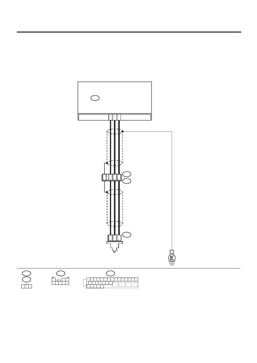
AG:DTC 56 ABNORMAL G SENSOR HIGH
Μ
Μ
Μ
Μ
OUTPUT
DIAGNOSIS:
• Faulty G sensor output voltage
TROUBLE SYMPTOM:
• ABS does not operate.
WIRING DIAGRAM:
ABS00312
F55
R70
F62
ABS CONTROL MODULE AND
HYDRAULIC CONTROL UNIT
ABS
G SENSOR
F49
2
1
3
F49
1 2 3 4 5 6 7 8 9 10 11 12 13 14 15
16 17 18 19 20 21 22
27 28 29 30 31
23
24
25
26
3
7
6
28
1
2
3
F55
R49
R70
2
8
30
1
2 3
4 5 6 7 8
ABS-143
ABS (DIAGNOSTICS)
DIAGNOSTICS CHART WITH SUBARU SELECT MONITOR
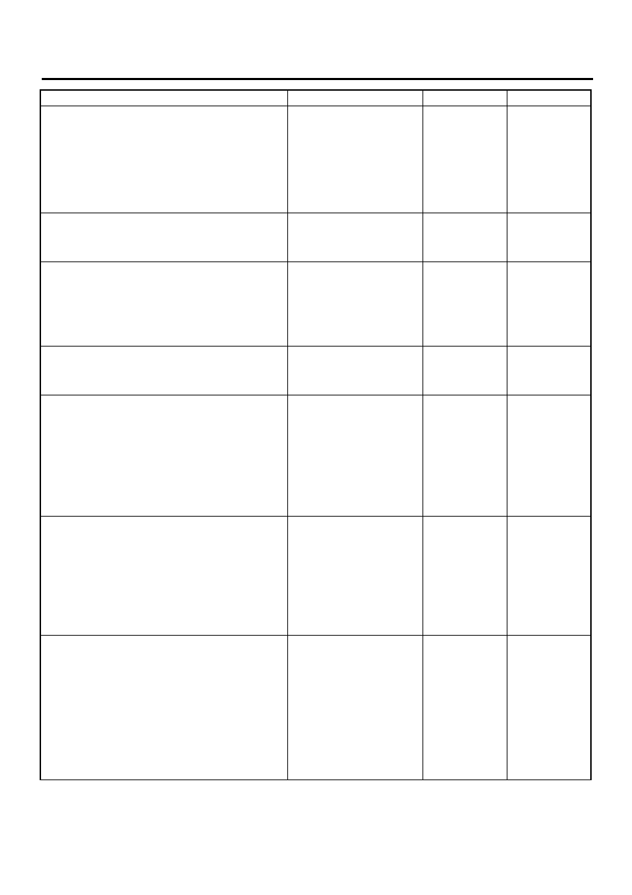
Step
Value
Yes
No
1
CHECK OUTPUT OF G SENSOR USING SE-
LECT MONITOR.
1) Select “Current data display & Save” on the
select monitor.
2) Read G sensor output on the select monitor
display.
Is the G sensor output on monitor display
within the specified range when the G sen-
sor is in horizontal position?
2.1 - 2.5 V
2
CHECK POOR CONTACT IN CONNECTORS.
Turn ignition switch to OFF.
Is there poor contact in connector between
ABSCM&H/U and G sensor?
There is no poor contact.
Repair connector.
3
CHECK ABSCM&H/U.
1) Connect all connectors.
2) Erase the memory.
3) Perform inspection mode.
4) Read out the DTC.
Is the same DTC still being output?
Same DTC is not indicated.
Replace
ABSCM&H/U.
<Ref. to ABS-6,
ABS Control Mod-
ule and Hydraulic
Control Unit
(ABSCM&H/U).>
4
CHECK ANY OTHER DTC APPEARANCE.
Are other DTC being output?
Other DTC is not indicated.
A temporary poor
contact.
Proceed with the
diagnosis corre-
sponding to the
DTC.
5
CHECK OPEN CIRCUIT IN G SENSOR OUT-
PUT HARNESS AND GROUND HARNESS.
1) Turn ignition switch to OFF.
2) Disconnect connector from ABSCM&H/U.
3) Measure resistance between ABSCM&H/U
connector terminals.
Connector & terminal
(F49) No. 6 — No. 28:
Is the measured value within the specified
range?
5.0 - 5.6 k
Ω
Repair harness/
connector
between G sensor
and ABSCM&H/U.
6
CHECK GROUND SHORT OF HARNESS.
Measure resistance between ABSCM&H/U
connector and chassis ground.
Connector & terminal
(F49) No. 28 — Chassis ground:
Does the measured value exceed the specified
value?
1 M
Ω
Repair harness
between G sensor
and ABSCM&H/U.
Replace
ABSCM&H/U.
<Ref. to ABS-6,
ABS Control Mod-
ule and Hydraulic
Control Unit
(ABSCM&H/U).>
7
CHECK G SENSOR.
1) Remove console box.
2) Remove G sensor from vehicle.
3) Connect connector to G sensor.
4) Connect connector to ABSCM&H/U.
5) Turn ignition switch to ON.
6) Measure voltage between G sensor con-
nector terminals.
Connector & terminal
(R70) No. 2 (+) — No. 3 (
−−−−
):
Is the voltage within the specified range
when G sensor is horizontal?
2.1 - 2.5 V
Replace G sen-
sor. <Ref. to ABS-
21, G Sensor.>
ABS-144
ABS (DIAGNOSTICS)
DIAGNOSTICS CHART WITH SUBARU SELECT MONITOR
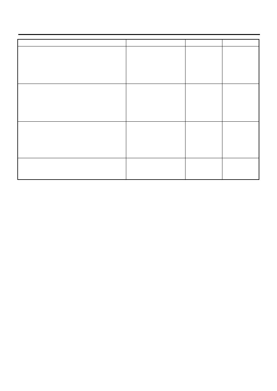
8
CHECK G SENSOR.
Measure voltage between G sensor connector
terminals.
Connector & terminal
(R70) No. 2 (+) — No. 3 (
−−−−
):
Is the voltage within the specified range when
G sensor is inclined forwards to 90
°
?
3.7 - 4.1 V
Replace G sen-
sor. <Ref. to ABS-
21, G Sensor.>
9
CHECK G SENSOR.
Measure voltage between G sensor connector
terminals.
Connector & terminal
(R70) No. 2 (+) — No. 3 (
−−−−
):
Is the voltage within the specified range when
G sensor is inclined backwards to 90
°
?
0.5 - 0.9 V
Replace G sen-
sor. <Ref. to ABS-
21, G Sensor.>
10
CHECK ABSCM&H/U.
1) Turn ignition switch to OFF.
2) Connect all connectors.
3) Erase the memory.
4) Perform inspection mode.
5) Read out the DTC.
Is the same DTC still being output?
Same DTC is not indicated.
Replace
ABSCM&H/U.
<Ref. to ABS-6,
ABS Control Mod-
ule and Hydraulic
Control Unit
(ABSCM&H/U).>
11
CHECK ANY OTHER DTC APPEARANCE.
Are other DTC being output?
Other DTC is not indicated.
A temporary poor
contact.
Proceed with the
diagnosis corre-
sponding to the
DTC.
Step
Value
Yes
No
ABS-145
ABS (DIAGNOSTICS)
DIAGNOSTICS CHART WITH SUBARU SELECT MONITOR
MEMO:
Нет комментариевНе стесняйтесь поделиться с нами вашим ценным мнением.
Текст