Subaru Legacy III (2000-2003 year). Service manual — part 656
RS-12
REAR SUSPENSION
REAR ARM
9) Install support sub frame front.
NOTE:
Check wheel alignment and adjust if necessary.
Tightening torque:
Refer to COMPONENT of General Descrip-
tion for tightening torque. <Ref. to RS-3,
REAR SUSPENSION, COMPONENT, Gen-
eral Description.>
C: DISASSEMBLY
1. FRONT BUSHING
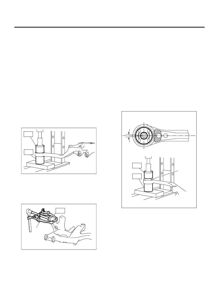
1) Using ST-A, B, press front bushing out of place.
ST-A, B
20099AE020INSTALLER & REMOVER
SET
(1) Set ST-A in position with larger inside diam-
eter side facing up.
(2) Set rear arm with protruded bushing side
facing down.
(3) Place ST-B on upper side of bushing, then
press bushing out of position.
2. REAR BUSHING
Using ST-C and bearing puller, press rear bushing
out of place.
ST-C
20099AE040INSTALLER & REMOVER
SET
D: ASSEMBLY
1. FRONT BUSHING
1) Using ST-A, B, press bushing into rear arm.
ST-A, B
20099AE020INSTALLER & REMOVER
SET
(1) Set ST-A in position with smaller inside di-
ameter side facing up.
(2) Set rear arm in position with outer side of ve-
hicle body facing down.
(3) Place bushing on upper side of rear arm.
(4) Place ST-B on upper side of bushing, then
press bushing into position.
CAUTION:
• Install bushing with painted side facing up.
• Install front bushing in the proper direction,
as shown in figure.
(1) Bearing puller
RS-00053
ST-B
ST-A
RS-00054
ST-C
( 1 )
(1) Bushing
0
˚±5
˚
RS-00055
( 1 )
ST-B
ST-A
RS-13
REAR SUSPENSION
REAR ARM
2. REAR BUSHING
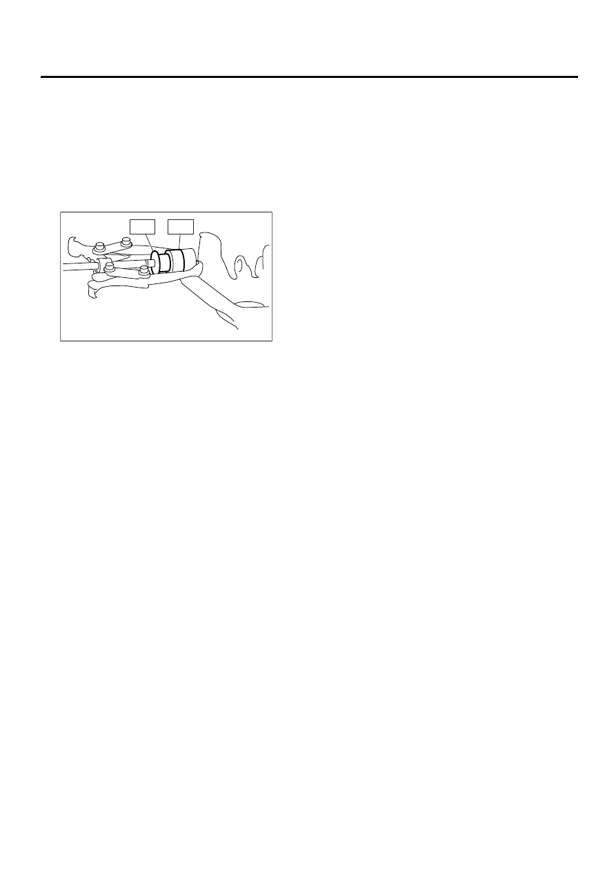
1) Using ST-C, D and bearing puller, press bushing
into rear arm.
ST-C, D
20099AE040INSTALLER & REMOVER
SET
(1) Insert bushing into bore in ST-D.
(2) Set ST-C, ST-D and bearing puller in posi-
tion, as shown in the figure, and press bushing
into position.
E: INSPECTION
Check rear arm for bends, corrosion or damage.
RS-00056
ST-C
ST-D
RS-14
REAR SUSPENSION
LINK UPPER
5. Link Upper
A: REMOVAL
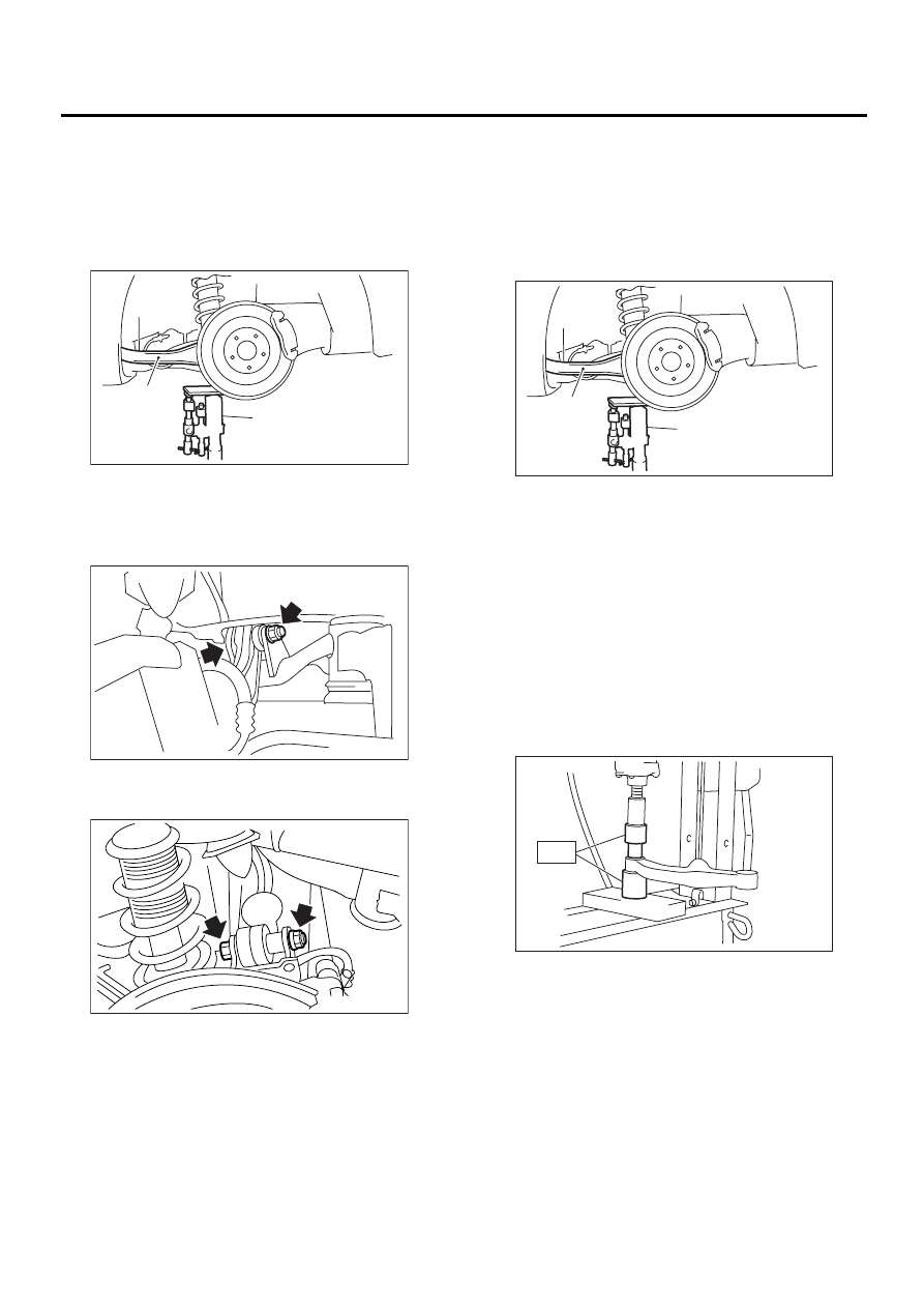
1) Loosen wheel nuts. Lift-up vehicle and remove
wheel.
2) Use transmission jack to support rear arm hori-
zontally.
3) Remove bolt securing link upper to sub frame.
4) Remove bolts which secure link upper to rear
arm and detach link upper.
B: INSTALLATION
Install in the reverse order of removal, observing
the following instructions.
CAUTION:
• Using transmission jack, support rear arm
horizontally, install link upper and tighten nuts
to specified torque.
• Tighten nut when installing adjusting bolt.
• Replace self-locking nut.
NOTE:
Check wheel alignment and adjust if necessary.
Tightening torque:
120 N·m (12.2 kgf-m, 88 ft-lb)
C: DISASSEMBLY
Using ST, press bushing out of place.
ST
20099AE010
INSTALLER & REMOVER
(1) Rear arm
(2) Transmission jack
RS-00052
( 1 )
( 2 )
RS-00058
RS-00059
(1) Rear arm
(2) Transmission jack
RS-00052
( 1 )
( 2 )
RS-00061
ST
RS-15
REAR SUSPENSION
LINK UPPER
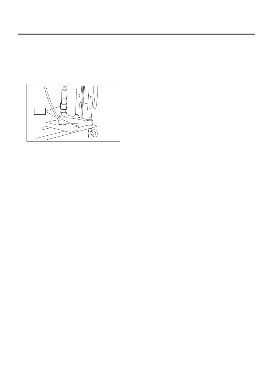
D: ASSEMBLY
1) Using ST, press bushing into place.
ST
20099AE010
INSTALLER & REMOVER
CAUTION:
Outer bushing has a “directional” design. Be
sure to install bushing with longer inner hous-
ing side facing vehicle rear.
E: INSPECTION
Visually check link upper for damage or bends.
RS-00090
ST
Нет комментариевНе стесняйтесь поделиться с нами вашим ценным мнением.
Текст