Subaru Legacy III (2000-2003 year). Service manual — part 657
RS-16
REAR SUSPENSION
REAR SHOCK ABSORBER
6. Rear Shock Absorber
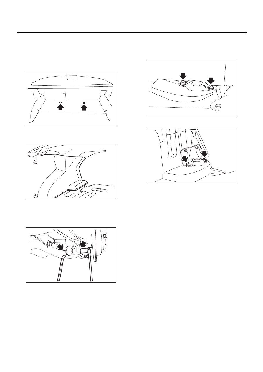
A: REMOVAL
1) Lift-up vehicle and remove rear wheels.
2) Remove clip and detach floor mat. (Wagon mod-
el)
3) Detach trunk mat. (Sedan model)
4) Roll up the trunk side trim. (Sedan model)
5) Remove bolt securing shock absorber to rear
arm.
6) Use a jack to support the shock absorber.
7) Remove nuts securing shock absorber mount to
body.
• Wagon
• Sedan
8) Remove shock absorber.
(1) Trunk side trim
RS-00063
RS-00064
( 1 )
RS-00065
RS-00066
RS-00067
RS-17
REAR SUSPENSION
REAR SHOCK ABSORBER
B: INSTALLATION
1) Use a jack to support the shock absorber.
2) Tighten self-locking nut used to secure shock
absorber to vehicle body.
CAUTION:
Use a new self-locking nut.
Tightening torque:
30 N·m (3.1 kgf-m, 22 ft-lb)
3) Place jack (furnished with vehicle) upside down
and position it between link rear and sub frame. Ad-
just jack position so rear shock absorber is aligned
with rear arm at their corresponding holes. Install
lower shock absorber bolts.
CAUTION:
Put a cloth between jack and its mating area to
protect link rear and sub frame from scratches.
4) Using transmission jack, support rear arm hori-
zontally and tighten shock absorber nuts and bolts
to specified torque.
Tightening torque:
160 N·m (16.3 kgf-m, 118 ft-lb)
CAUTION:
Use a new self-locking nut.
5) Install floor mat. (Wagon model)
6) Set trunk side trim. (Sedan model)
7) Install trunk mat. (Sedan model)
NOTE:
Check wheel alignment and adjust if necessary.
C: DISASSEMBLY
For disassembly of shock absorber, refer to proce-
dures outlined under front strut as a guide.
<Ref. to FS-18, DISASSEMBLY, Front Strut.>
D: ASSEMBLY
Refer to Front Strut as a guide for assembly proce-
dures.
<Ref. to FS-18, ASSEMBLY, Front Strut.>
E: INSPECTION
Refer to Front Strut as a guide for inspection proce-
dures.
<Ref. to FS-19, INSPECTION, Front Strut.>
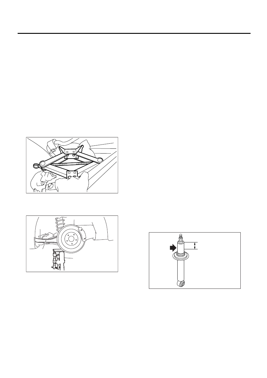
F: DISPOSAL
CAUTION:
• Before handling shock absorber, be sure to
wear goggles to protect eyes from gas, oil and/
or filings.
• Completely discharge the gas from the shock
absorber before disposal. Follow the disposal
procedure outlined below.
• Do not disassemble shock absorber or place
into a fire.
• Drill holes before disposing of shock absorb-
er.
1) Place shock absorber on a flat and level surface
with piston rod fully extended.
2) Using a 2 to 3 mm (0.08 to 0.12 in) dia. drill, drill
30 mm (1.18 in) deep holes in areas shown in the
figure.
(1) Rear arm
(2) Transmission jack
RS-00051
RS-00052
( 1 )
( 2 )
RS-00070
40 mm (1.57 in)
RS-18
REAR SUSPENSION
LINK FRONT
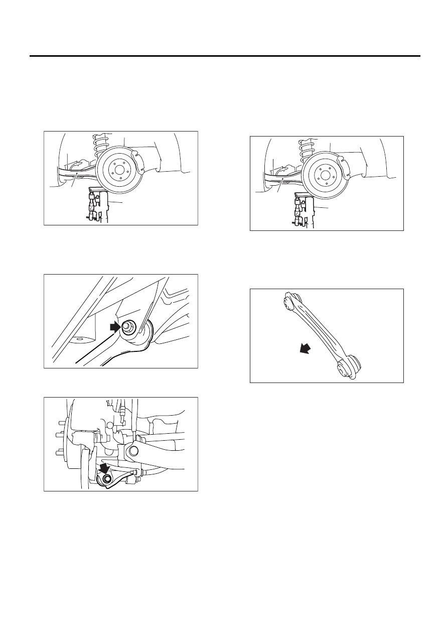
7. Link Front
A: REMOVAL
1) Loosen wheel nuts. Lift-up vehicle and remove
wheel.
2) Use transmission jack to support rear arm hori-
zontally.
3) Remove bolt securing link front to sub frame.
4) Remove bolts which secure link front to rear arm
and detach link front.
NOTE:
Link front bushing cannot be replaced alone. Al-
ways replace link front and bushing as a single unit.
B: INSTALLATION
Install in the reverse order of removal, observing
the following instructions.
CAUTION:
• Using transmission jack, support rear arm
horizontally, install link front and tighten nuts
to specified torque.
• Install link front with protruded side facing
front.
• Replace self-locking nut.
NOTE:
Check wheel alignment and adjust if necessary.
Tightening torque:
120 N·m (12.2 kgf-m, 88 ft-lb)
C: INSPECTION
Visually check link front for damage or bends.
(1) Rear arm
(2) Transmission jack
RS-00052
( 1 )
( 2 )
RS-00072
RS-00073
(1) Rear arm
(2) Transmission jack
(1) Front
RS-00052
( 1 )
( 2 )
RS-00075
( 1 )
RS-19
REAR SUSPENSION
LINK REAR
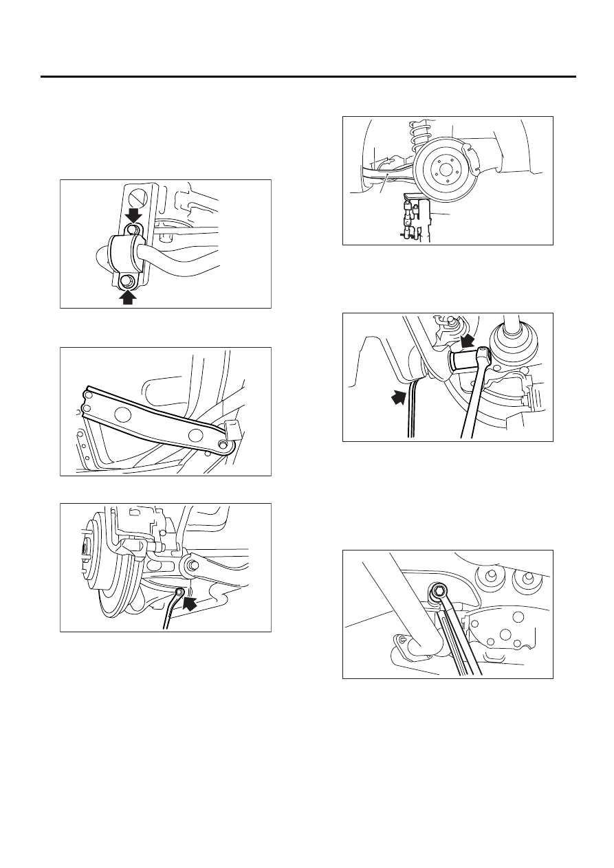
8. Link Rear
A: REMOVAL
1) Loosen wheel nuts. Lift-up vehicle and remove
wheel.
2) Remove bolt securing stabilizer clamps to sub
frame.
3) Remove support sub frame RH. (When remov-
ing RH side link rear.)
4) Remove stabilizer link.
5) Use transmission jack to support rear arm hori-
zontally.
6) Remove bolt securing link rear to rear arm.
7) Scribe an alignment mark on link rear adjusting
bolt and sub frame.
8) Remove bolts securing link rear to sub frame,
detach link rear.
CAUTION:
To loosen adjusting bolt, always loosen nut
while holding the head of adjusting bolt.
RS-00039
RS-00077
RS-00038
(1) Rear arm
(2) Transmission jack
RS-00052
( 1 )
( 2 )
RS-00080
RS-00081
Нет комментариевНе стесняйтесь поделиться с нами вашим ценным мнением.
Текст