Subaru Legacy III (2000-2003 year). Service manual — part 655
RS-8
REAR SUSPENSION
WHEEL ALIGNMENT
2. Wheel Alignment
A: INSPECTION
NOTE:
The front and rear wheel alignment must be mea-
sured and/or adjusted at once to obtain accuracy.
Measure and/or adjust the rear wheel alignment to-
gether with the front.
Follow the procedure in “FS” section “Wheel Align-
ment” for measurement and/or adjustment of wheel
alignment. <Ref. to FS-6, Wheel Alignment.>
RS-9
REAR SUSPENSION
REAR STABILIZER
3. Rear Stabilizer
A: REMOVAL
1) Jack-up the rear part of the vehicle, support it
with safety stands (rigid racks).
2) Remove bolts which secure stabilizer link to rear
arm.
3) Remove bolts which secure stabilizer to sub
frame.
B: INSTALLATION
Install in the reverse order of removal.
NOTE:
Ensure that bushing and stabilizer have the same
identification colors when installing.
CAUTION:
Discard old self-locking nut and replace with a
new one.
Tightening torque:
Stabilizer link to rear arm
44 N·m (4.5 kgf-m, 32.5 ft-lb)
Clamp to sub frame
40 N·m (4.1 kgf-m, 30 ft-lb)
C: INSPECTION
1) Check bushing for cracks, fatigue or damage.
2) Check stabilizer links for deformities, cracks, or
damage, and bushing for protrusions from the hole
of stabilizer link.
RS-00038
RS-00039
RS-10
REAR SUSPENSION
REAR ARM
4. Rear Arm
A: REMOVAL
1) Lift-up the vehicle and remove rear wheel.
2) Remove support sub frame front.
<Ref. to RS-21, REMOVAL, Support Sub Frame
Front.>
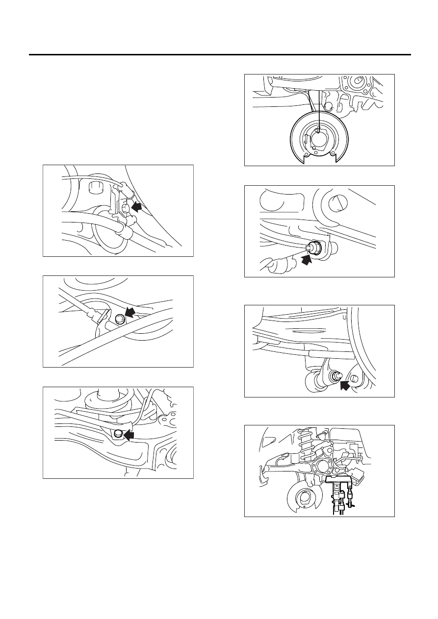
3) Remove bearing unit.
<Ref. to DS-23, REMOVAL, Hub Unit Bearing.>
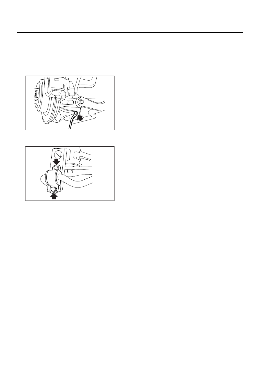
4) Remove bolt securing parking brake cable
clamp to rear arm.
5) Remove bolt securing brake hose to rear arm.
6) Remove bolt securing ABS sensor to rear arm.
7) Suspend the back plate from sub frame.
8) Remove nut securing stabilizer link to rear arm.
9) Remove bolt securing shock absorber to rear
arm.
10) Use transmission jack to support rear arm hor-
izontally.
RS-00040
RS-00041
RS-00042
RS-00043
RS-00044
RS-00045
RS-00046
RS-11
REAR SUSPENSION
REAR ARM
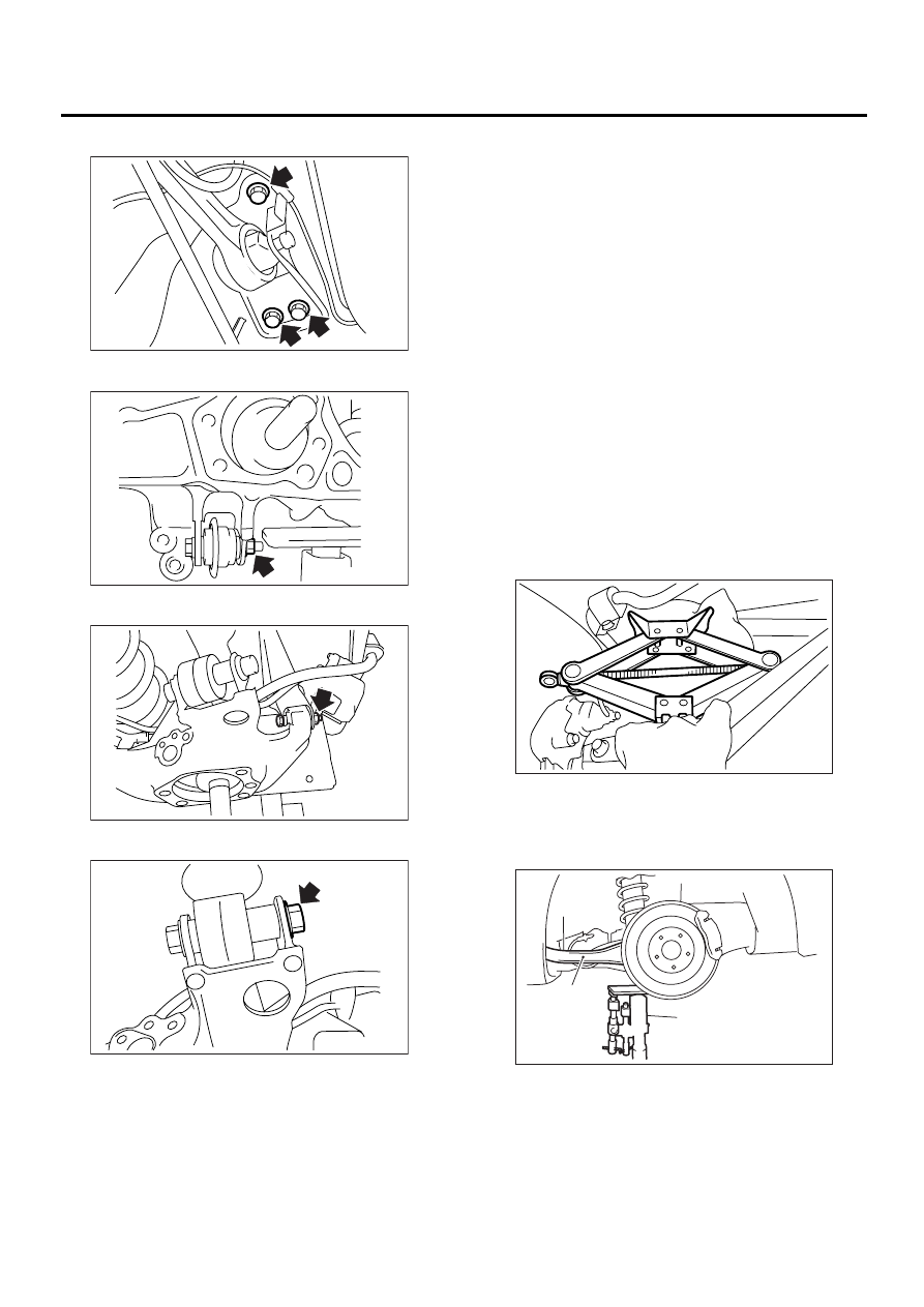
11) Remove bolt securing rear arm to body.
12) Loosen nut securing link front to rear arm.
13) Loosen nut securing link rear to rear arm.
14) Loosen nut securing link upper to rear arm.
15) Remove bolts securing rear arm to links and re-
move rear arm.
B: INSTALLATION
CAUTION:
Discard old self-locking nut and replace with a
new one.
1) Use a transmission jack to support the rear arm.
2) Install rear arm and temporarily tighten bolts se-
curing rear arm to links.
3) Install bearing unit.
<Ref. to DS-24, INSTALLATION, Hub Unit Bear-
ing.>
4) Install bolt securing ABS sensor to rear arm.
5) Install bolt securing brake hose to rear arm.
6) Install bolt securing parking brake cable clamp to
rear arm.
7) Place jack (furnished with vehicle) upside down
and position it between link rear and sub frame. Ad-
just jack position so rear shock absorber is aligned
with rear arm at their corresponding holes. Install
lower shock absorber bolts.
CAUTION:
Put a cloth between jack and its mating area to
protect link rear and sub frame from scratches.
8) Using transmission jack, support rear arm hori-
zontally and tighten nuts and bolts securing rear
arm, link front, link rear, link upper and shock ab-
sorber.
RS-00047
RS-00048
RS-00049
RS-00050
(1) Rear arm
(2) Transmission jack
RS-00051
RS-00052
( 1 )
( 2 )
Нет комментариевНе стесняйтесь поделиться с нами вашим ценным мнением.
Текст