Subaru Legacy III (2000-2003 year). Service manual — part 885
AC-76
HVAC SYSTEM (AUTO A/C) (DIAGNOSTICS)
DIAGNOSTIC PROCEDURE WITH DIAGNOSTIC TROUBLE CODE (DTC) (RHD
MODEL)
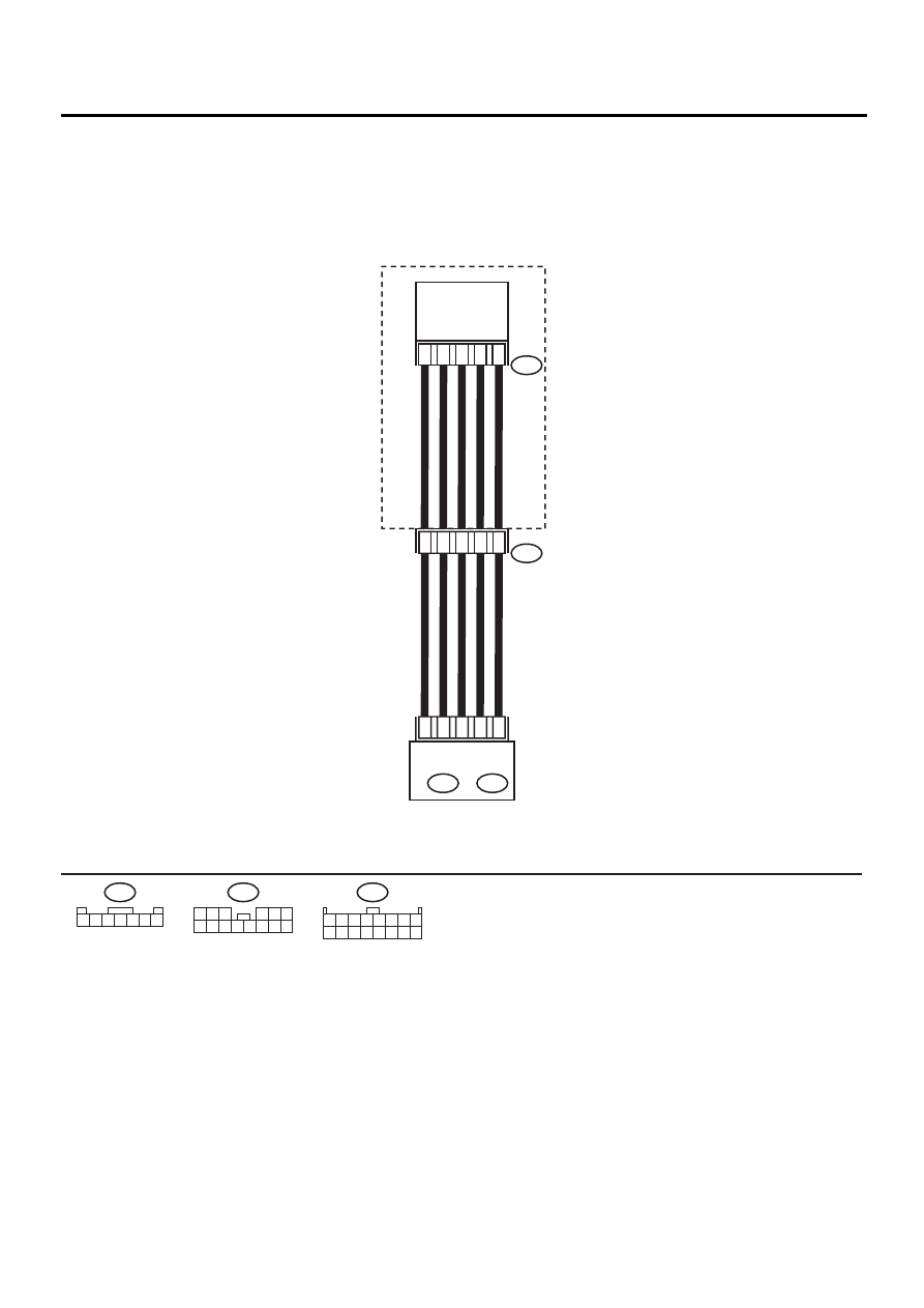
F: DTC 28 OR 29 (MODE DOOR ACTUATOR POTENTIOMETER LINE)
WIRING DIAGRAM:
1
3
5
6
7
E
i45
MODE DOOR
ACTUATOR
3
11
4
1
2
A10
A5
A14
A16
A8
HEATER MODULE
AUTO A/C
CONTROL MODULE
A: i48
B: i49
E
1 2 3 4 5 6 7
i48
1 2 3 4 5 6 7 8
9 10 11 12 13 14 15 16
A:
i45
1 2 3
4 5 6
7 8 9 10 11 12 13 14
AC-00377
AC-77
HVAC SYSTEM (AUTO A/C) (DIAGNOSTICS)
DIAGNOSTIC PROCEDURE WITH DIAGNOSTIC TROUBLE CODE (DTC) (RHD
MODEL)
Step
Value
Yes
No
1
CHECK MODE DOOR ACTUATOR.
1) Turn ignition switch to OFF.
2) Remove mode door actuator.
3) Make sure that mode door actuator is oper-
ated when connecting battery positive (+)
terminal to terminal No. 6 and negative (-)
terminal to terminal No. 7 of mode door
actuator.
Does the mode door actuator operate?
Ventilation motor operates.
Replace mode
door actuator.
2
CHECK POTENTIOMETER.
Measure resistance for the power supply line
of the potentiometer.
Terminals
(E) No. 1 — No. 3:
Is the measured value same as the specified
value?
Approx. 6.0 k
Ω
Replace mode
door actuator.
3
CHECK POTENTIOMETER.
Measure resistance for the signal line of the
potentiometer, when the lever is in the FULL
VENT position.
Terminals
(E) No. 1 — No. 5:
Is the measured value same as the specified
value?
Approx. 1.2 k
Ω
Replace mode
door actuator.
4
CHECK POTENTIOMETER.
Measure resistance for the signal line of the
potentiometer, when the lever is in the FULL
DEF position.
Terminals
(E) No. 1 — No. 5:
Is the measured value same as the specified
value?
Approx. 4.5 k
Ω
Replace mode
door actuator.
5
CHECK HARNESS CONNECTOR BETWEEN
A/C CONTROL MODULE AND MODE DOOR
ACTUATOR.
1) Disconnect connector from A/C control
module.
2) Measure resistance of harness between A/
C control module and mode door actuator.
Connector & terminal
(i48) No. 14 — (E) No. 5:
Is the measured value less than the speci-
fied value?
1
Ω
Repair harness
between A/C con-
trol module and
mode door actua-
tor.
6
CHECK HARNESS CONNECTOR BETWEEN
A/C CONTROL MODULE AND MODE DOOR
ACTUATOR.
Measure resistance of harness between A/C
control module and mode door actuator.
Connector & terminal
(i48) No. 5 — (E ) No. 3:
Is the measured value less than the specified
value?
1
Ω
Repair harness
between A/C con-
trol module and
mode door actua-
tor.

AC-78
HVAC SYSTEM (AUTO A/C) (DIAGNOSTICS)
DIAGNOSTIC PROCEDURE WITH DIAGNOSTIC TROUBLE CODE (DTC) (RHD
MODEL)
7
CHECK HARNESS CONNECTOR BETWEEN
A/C CONTROL MODULE AND MODE DOOR
ACTUATOR.
Measure resistance of harness between A/C
control module and mode door actuator.
Connector & terminal
(i48) No. 10 — (E) No. 1:
Is the measured value less than the specified
value?
1
Ω
Repair harness
between A/C con-
trol module and
mode door actua-
tor.
8
CHECK HARNESS CONNECTOR BETWEEN
A/C CONTROL MODULE AND MODE DOOR
ACTUATOR.
Measure resistance of harness between A/C
control module and mode door actuator.
Connector & terminal
(i48) No. 8 — (E) No. 7:
Is the measured value less than the specified
value?
1
Ω
Repair harness
between A/C con-
trol module and
mode door actua-
tor.
9
CHECK HARNESS CONNECTOR BETWEEN
A/C CONTROL MODULE AND MODE DOOR
ACTUATOR.
Measure resistance of harness between A/C
control module and mode door actuator.
Connector & terminal
(i48) No. 16 — (E) No. 6:
Is the measured value less than the specified
value?
1
Ω
Repair harness
between A/C con-
trol module and
mode door actua-
tor.
10
CHECK POOR CONTACT.
Check poor contact in A/C control module.
Is there poor connection in connector?
There is no poor connection.
Replace A/C con-
trol module.
Repair connector.
Step
Value
Yes
No
AC-79
HVAC SYSTEM (AUTO A/C) (DIAGNOSTICS)
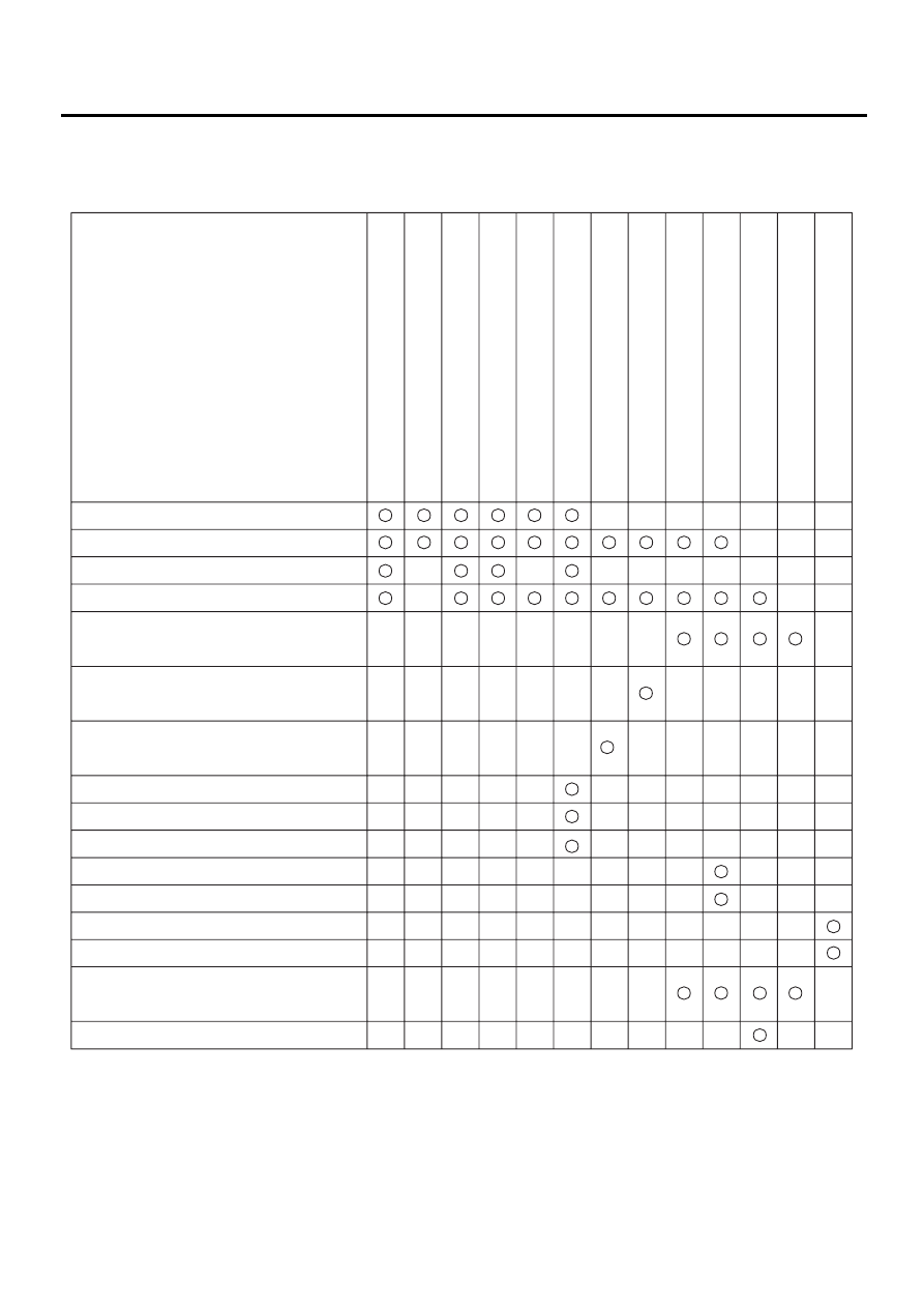
SYMPTOM RELATED DIAGNOSTIC
12.Symptom Related Diagnostic
A: GENERAL DIAGNOSTICS TABLE
AC-00378
Air mix door actuator and potentiometer
(including links)
Mode door actuator and potentiometer
(including links)
Intake door actuator and
potentiometer (including links)
Fuses (M/B No. 2, F/B No. 17)
Poor connector contacts
Ground
A/C control module
Blower fan motor
Power transistor & fuse
Blower fan relay
A/C relay
Magnet clutch
Radiator fan motors (Main and sub)
Radiator fan relays (Main and sub)
In-vehicle sensor aspirator duct
Sensors (In-vehicle, ambient, water temperature,
evaporator, sunload, etc.)
Component parts
Symptom
Previous mode immediately before
resetting operation is not retained in memory.
A/C system fails to operate when
IG SW is turned "ON".
Burned-out fuse.
No indication appears on display.
Blower motor does not rotate or
rotates erroneously.
Compartment temperature does not decrease
(No cool air is discharged).
Air vents cannot be switched.
Compartment temperature does not quickly
respond to the set value.
Illumination does not dim at night.
A/C does not change from
"Fresh" to "Recirc" or vise versa.
Compartment temperature is higher than
or lower than the set value.
Compartment temperature does not increase
(No hot air is discharged).
Condenser fan does not operate
during A/C operation.
Нет комментариевНе стесняйтесь поделиться с нами вашим ценным мнением.
Текст