Subaru Legacy III (2000-2003 year). Service manual — part 632
MT-96
MANUAL TRANSMISSION AND DIFFERENTIAL
FRONT DIFFERENTIAL ASSEMBLY
C: DISASSEMBLY
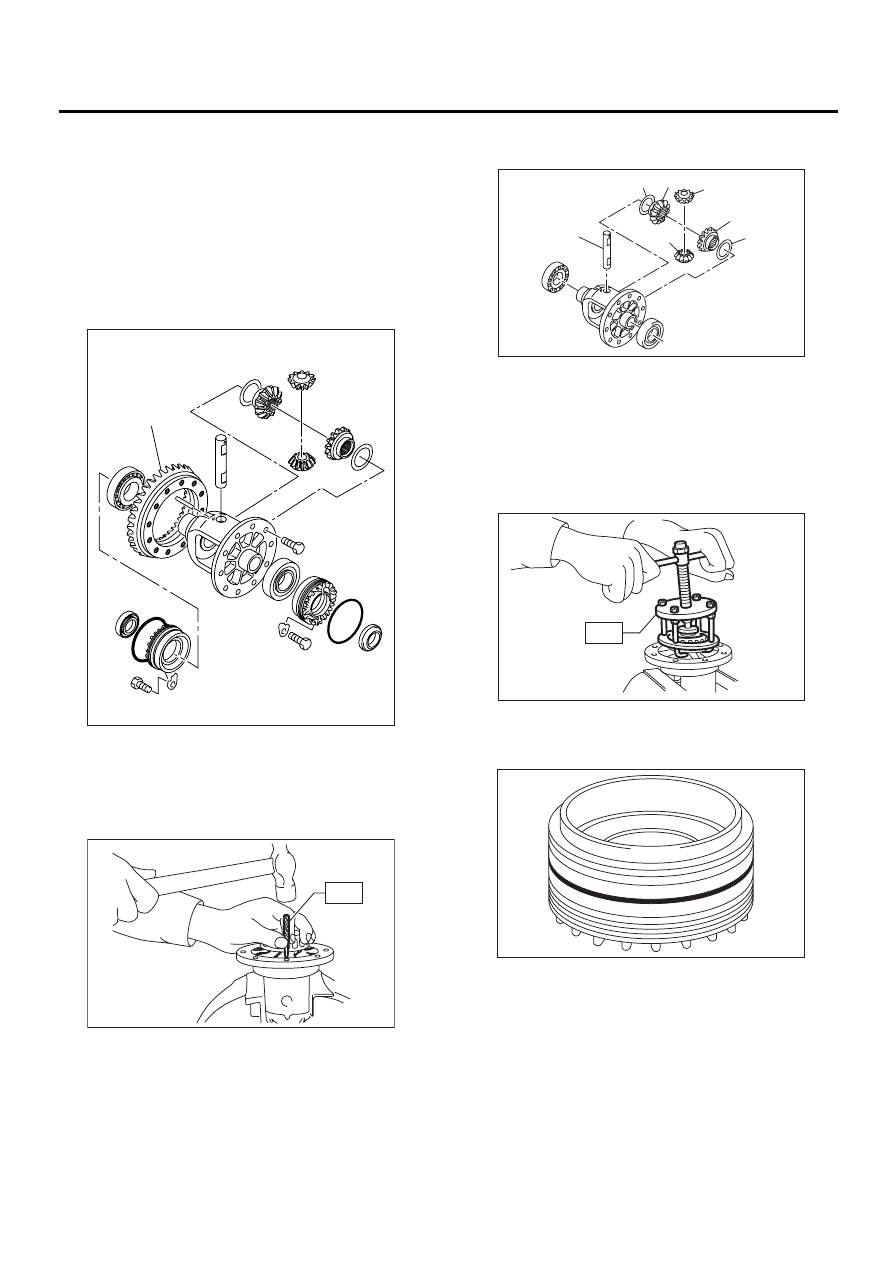
1. DIFFERENTIAL CASE ASSEMBLY
1) Remove right and left snap rings from differen-
tial, and then remove two axle drive shafts.
NOTE:
During reassembly, reinstall each axle drive shaft
in the same place from which it was removed.
2) Loosen twelve bolts and remove hypoid driven
gear.
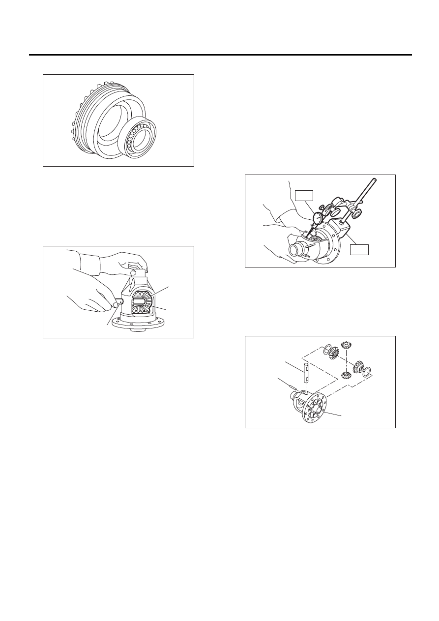
3) Drive out straight pin from differential assembly
toward hypoid driven gear.
ST
899904100
REMOVER
4) Pull out pinion shaft, and remove differential
bevel pinion and gear and washer.
5) Remove roller bearing using ST.
ST
399527700
PULLER SET
2. SIDE RETAINER
1) Remove O-ring.
(A) Hypoid driven gear
(A)
MT-00275
MT-00276
ST
(A) Pinion shaft
(B) Bevel pinion
(C) Bevel gear
(D) Washer
( A )
( B )
( B )
( C )
( C )
( D )
( D )
MT-00277
MT-00278
ST
MT-00279
MT-97
MANUAL TRANSMISSION AND DIFFERENTIAL
FRONT DIFFERENTIAL ASSEMBLY
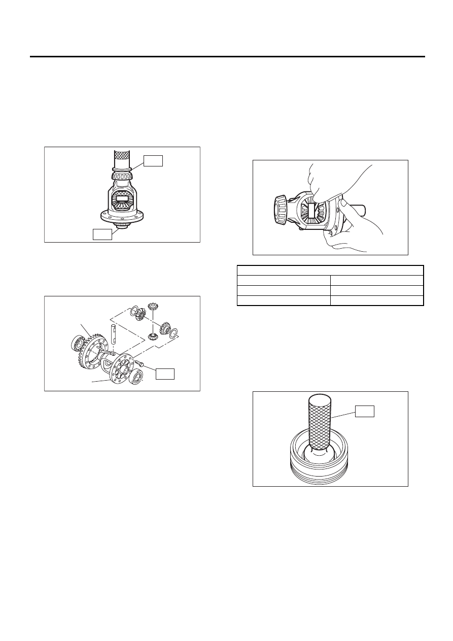
2) Remove oil seal.
D: ASSEMBLY
1. DIFFERENTIAL CASE ASSEMBLY
1) Install bevel gear and bevel pinion together with
washers, and insert pinion shaft.
NOTE:
Face the chamfered side of washer toward gear.
2) Measure backlash between bevel gear and pin-
ion. If it is not within specifications, install a suitable
washer to adjust it. <Ref. to MT-100, ADJUST-
MENT, Front Differential Assembly.>
NOTE:
Be sure the pinion gear tooth contacts adjacent
gear teeth during measurement.
ST1
498247001
MAGNET BASE
ST2
498247100
DIAL GAUGE
Standard backlash:
0.13 — 0.18 mm (0.0051 — 0.0071 in)
3) Align pinion shaft and differential case at their
holes, and drive straight pin into holes from the hy-
poid driven gear side, using ST.
NOTE:
Lock straight pin after installing.
ST
899904100
REMOVER
(A) Bevel pinion
(B) Bevel gear
(C) Pinion shaft
MT-00363
( B )
( A )
( C )
MT-00284
(A) Pinion shaft
(B) Differential case
(C) Straight pin
MT-00285
ST1
ST2
MT-00286
( A )
( B )
( C )
MT-98
MANUAL TRANSMISSION AND DIFFERENTIAL
FRONT DIFFERENTIAL ASSEMBLY
4) Install roller bearing to differential case.
NOTE:
• Do not apply pressure in excess of 10 kN (1 ton,
1.1 US ton, 1.0 Imp ton).
• Be careful because roller bearing outer races are
used as a set.
ST1
499277100
BUSHING 1-2 INSTALLER
ST2
398497701
ADAPTER
5) Install hypoid driven gear to differential case us-
ing twelve bolts.
Tightening torque:
T: 62 N·m (6.3 kgf-m, 45.6 ft-lb)
6) Position drive axle shaft in differential case and
hold it with outer snap ring (28). Using a thickness
gauge, measure clearance between the shaft and
case is within specifications.
NOTE:
It it is not within specifications, replace snap ring
with a suitable one.
Clearance:
0 — 0.25 mm (0 — 0.0098 in)
2. SIDE RETAINER
1) Install bearing outer race to side retainer.
NOTE:
Press-in while being careful not to scratch side re-
tainer and bearing outer race.
2) Install new oil seal.
ST
499797000
INSTALLER
(A) Hypoid driven gear
(B) Differential case
MT-00287
ST1
ST2
MT-00288
( A )
( B )
T
Snap ring (Outer-28)
Part No.
Thickness mm (in)
805028011
1.05 (0.0413)
805028012
1.20 (0.0472)
MT-00365
MT-00364
ST
MT-99
MANUAL TRANSMISSION AND DIFFERENTIAL
FRONT DIFFERENTIAL ASSEMBLY
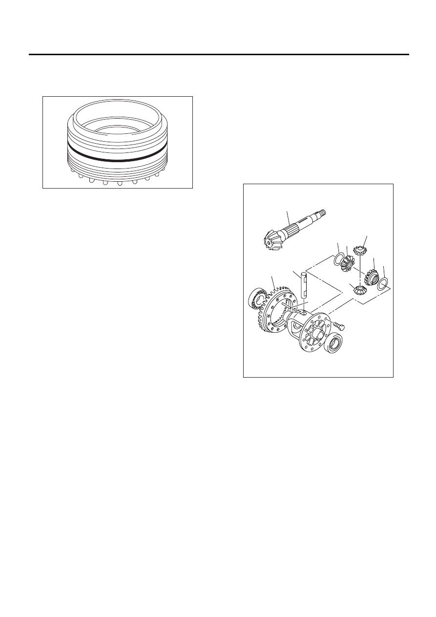
3) Install new O-ring.
NOTE:
Do not stretch or damage O-ring.
E: INSPECTION
Repair or replace the differential gear in the follow-
ing cases:
• The hypoid drive gear and drive pinion shaft
tooth surface are damaged, excessively worn, or
seized.
• The roller bearing on the drive pinion shaft has a
worn or damaged roller path.
• There is damage, wear, or seizure of the differ-
ential bevel pinion, differential bevel gear, washer,
pinion shaft, and straight pin.
• The differential case has worn or damaged slid-
ing surfaces.
MT-00279
(A) Drive pinion shaft
(B) Hypoid driven gear
(C) Pinion shaft
(D) Straight pin
(E) Washer
(F) Differential bevel gear
(G) Differential bevel pinion
MT-00291
(A)
(B)
(C)
(E)
(E)
(F)
(F)
(G)
(G)
(D)
Нет комментариевНе стесняйтесь поделиться с нами вашим ценным мнением.
Текст