Subaru Legacy III (2000-2003 year). Service manual — part 630
MT-88
MANUAL TRANSMISSION AND DIFFERENTIAL
DRIVE PINION SHAFT ASSEMBLY
8) Select one to three shims from the next table for
the value determined as described above and take
a shim thickness which is closest to the said value.
9) Install differential assembly. <Ref. to MT-95, IN-
STALLATION, Front Differential Assembly.>
10) Set transmission main shaft assembly and
drive pinion assembly in position. (So there is no
clearance between the two when moved all the way
to the front). Inspect suitable 1st — 2nd, 3rd — 4th
and 5th shifter fork so that coupling sleeve and re-
verse driven gear are positioned in the center of
their synchronizing mechanisms. <Ref. to MT-92,
INSPECTION, Drive Pinion Shaft Assembly.>
11) Install transmission case. <Ref. to MT-61, IN-
STALLATION, Transmission Case.>
12) Install transfer case with extension case as-
sembly. <Ref. to MT-47, INSTALLATION, Transfer
Case and Extension Case Assembly.>
13) Install the manual transmission assembly to ve-
hicle. <Ref. to MT-35, INSTALLATION, Manual
Transmission Assembly.>
C: DISASSEMBLY
NOTE:
Attach a cloth to the end of driven shaft (on the fric-
tional side of thrust needle bearing) during disas-
sembly or reassembly to prevent damage.
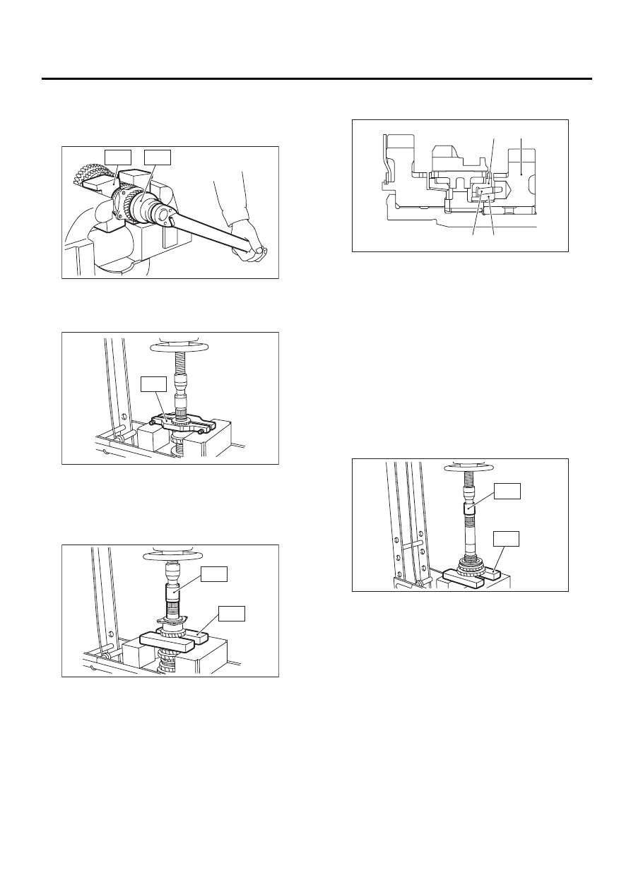
1) Straighten lock nut at staked portion. Remove
the lock nut using ST1, ST2 and ST3.
ST1
899884100
HOLDER
ST2
498427100
STOPPER
ST3
899988608
SOCKET WRENCH
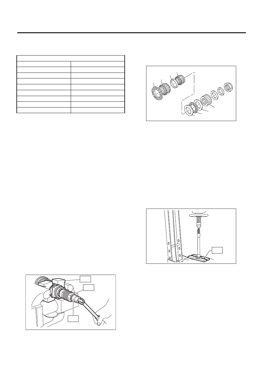
2) Withdraw drive pinion from driven shaft.
Remove differential bevel gear sleeve, adjusting
washer No. 1, adjusting washer No. 2, thrust bear-
ing, needle bearing, drive pinion collar, needle
bearing and thrust bearing.
3) Remove roller bearing and washer using ST and
press.
NOTE:
Do not reuse roller bearing.
ST
498077000
REMOVER
Drive pinion shim
Part No.
Thickness mm (in)
32295AA031
0.150 (0.0059)
32295AA041
0.175 (0.0069)
32295AA051
0.200 (0.0079)
32295AA061
0.225 (0.0089)
32295AA071
0.250 (0.0098)
32295AA081
0.275 (0.0108)
32295AA091
0.300 (0.0118)
32295AA101
0.500 (0.0197)
MT-00244
ST2
ST3
ST1
(A) Differential bevel gear sleeve
(B) Washer No. 1 (25
×
37.5
×
t)
(C) Thrust bearing (25
×
37.5
×
3)
(D) Washer No. 2 (25
×
37.5
×
4)
(E) Needle bearing (25
×
30
×
20)
(F) Drive pinion collar
(G) Needle bearing (30
×
37
×
23)
(H) Thrust bearing (33
×
50
×
3)
MT-00245
( H )
( G )
( F )
( E )
( D )
( C )
( B )
( A )
MT-00246
ST
MT-89
MANUAL TRANSMISSION AND DIFFERENTIAL
DRIVE PINION SHAFT ASSEMBLY
4) Straighten lock nut at staked portion. Remove
the lock nut using ST1 and ST2.
ST1
499987300
SOCKET WRENCH (50)
ST2
899884100
HOLDER
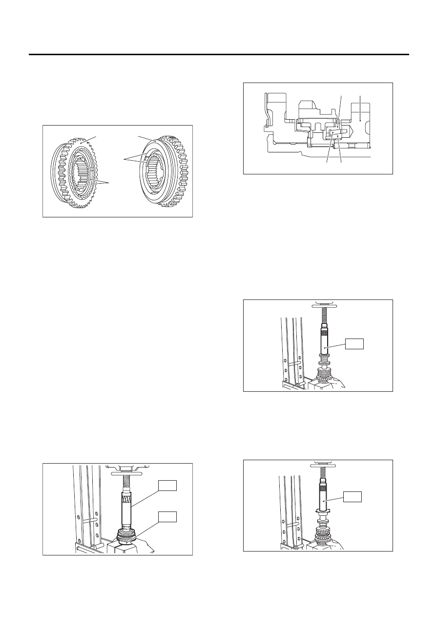
5) Remove 5th driven gear using ST.
ST
499857000
5TH DRIVEN GEAR REMOV-
ER
6) Remove woodruff key.
7) Remove roller bearing, 3rd-4th driven gear using
ST1 and ST2.
ST1
499757002
INSTALLER
ST2
899714110
REMOVER
8) Remove the key.
9) Remove 2nd driven gear, inner baulk ring, syn-
chro cone and outer baulk ring.
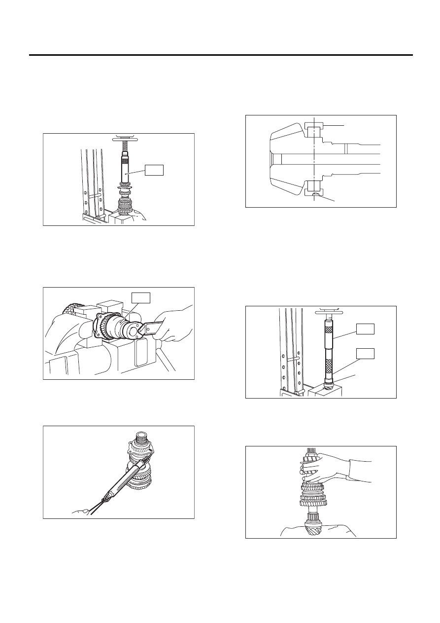
10) Remove 1st driven gear, 2nd gear bushing,
gear and hub using ST1 and ST2.
NOTE:
Replace gear and hub if necessary. Do not attempt
to disassemble if at all possible because they must
engage at a specified point. If they have to be dis-
assembled, mark the engaging point beforehand.
ST1
499757002
INSTALLER
ST2
899714110
REMOVER
11) Remove sub gear for 1st driven gear.
MT-00247
ST2
ST1
MT-00248
ST
MT-00249
ST1
ST2
(A) 2nd driven gear
(B) Inner baulk ring
(C) Synchro cone
(D) Outer baulk ring
MT-00250
( A )
( D )
( B )
( C )
MT-00251
ST1
ST2
MT-90
MANUAL TRANSMISSION AND DIFFERENTIAL
DRIVE PINION SHAFT ASSEMBLY
D: ASSEMBLY
1) Install sleeve and assembly by matching align-
ment marks.
NOTE:
• Use new gear and hub assembly, if gear or hub
have been replaced.
2) Install washer, snap ring and sub gear (except
for Europe model) to 1st driven gear.
3) Install 1st driven gear, 1st baulk ring, gear and
hub assembly onto driven shaft.
NOTE:
• Take care to install gear and hub assembly in
proper direction.
• Align baulk ring and gear & hub assembly with
key groove.
4) Install 2nd driven gear bushing onto driven shaft
using ST1, ST2 and press.
NOTE:
• Do not apply pressure in excess of 10 kN (1 ton,
1.1 US ton, 1.0 Imp ton).
• Attach a cloth to the end of driven shaft to pre-
vent damage.
• When press fitting, align oil holes of shaft and
bush.
ST1
499277200
INSTALLER
ST2
499587000
INSTALLER
5) Install 2nd driven gear, inner baulk ring, synchro
cone, outer baulk ring and insert onto driven shaft.
6) After installing key on driven shaft, install 3rd-4th
driven gear using ST and press.
NOTE:
• Do not apply pressure in excess of 10 kN (1 ton,
1.1 US ton, 1.0 Imp ton).
• Align groove in baulk ring with insert.
ST
499277200
INSTALLER
7) Install a set of roller bearings onto the driven
shaft using ST and press.
NOTE:
Do not apply pressure in excess of 10 kN (1 ton, 1.1
US ton, 1.0 Imp ton).
ST
499277200
INSTALLER
(A) 1st gear side
(B) 2nd gear side
(C) Flush surface
(D) Stepped surface
MT-00252
( B )
( A )
( C )
( D )
MT-00253
ST1
ST2
(A) 2nd driven gear
(B) Inner baulk ring
(C) Synchro cone
(D) Outer baulk ring
MT-00254
( A )
( D )
( B )
( C )
MT-00255
ST
MT-00256
ST
MT-91
MANUAL TRANSMISSION AND DIFFERENTIAL
DRIVE PINION SHAFT ASSEMBLY
8) Position woodruff key in groove on the rear of
driven shaft. Install 5th driven gear onto drive shaft
using ST and press.
NOTE:
Do not apply pressure in excess of 10 kN (1 ton, 1.1
US ton, 1.0 Imp ton).
ST
499277200
INSTALLER
9) Install lock washer. Install lock nut and tighten to
the specified torque using ST.
ST
499987300
SOCKET WRENCH (50)
Tightening torque:
260 N·m (26.5 kgf-m, 192 ft-lb)
10) Stake lock nut at two points.
11) Using spring balancer, check that starting
torque of roller bearing is 0.1 to 1.5 N (0.01 to 0.15
kgf, 0.02 to 0.33ft).
12) Install roller bearing onto drive pinion.
NOTE:
When installing roller bearing, note its directions
(front and rear) because knock pin hole in outer
race is offset.
13) Install washer using ST1, ST2 and press.
NOTE:
Do not apply pressure in excess of 10 kN (1 ton, 1.1
US ton, 1.0 Imp ton).
ST1
499277100
BUSHING 1-2 INSTALLER
ST2
499277200
INSTALLER
14) Install thrust bearing and needle bearing. Install
driven shaft assembly.
MT-00257
ST
MT-00258
ST
MT-00259
(A) Roller bearing
(B) Knock pin hole
(A) Washer
MT-00260
( A )
( B )
( A )
ST2
ST1
MT-00261
MT-00262
Нет комментариевНе стесняйтесь поделиться с нами вашим ценным мнением.
Текст