Subaru Legacy III (2000-2003 year). Service manual — part 633
MT-100
MANUAL TRANSMISSION AND DIFFERENTIAL
FRONT DIFFERENTIAL ASSEMBLY
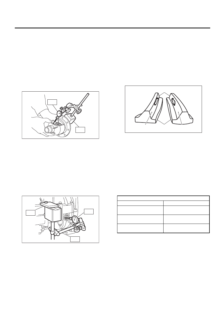
1. BEVEL PINION GEAR BACKLASH
Measure backlash between bevel gear and pinion.
If it is not within specifications, install a suitable
washer to adjust it.
NOTE:
Be sure the pinion gear tooth contacts adjacent
gear teeth during measurement.
ST1
498247001
MAGNET BASE
ST2
498247100
DIAL GAUGE
Standard backlash:
0.13 — 0.18 mm (0.0051 — 0.0071 in)
2. HYPOID GEAR BACKLASH
Set ST1, ST2 and ST3. Insert the needle through
transmission oil drain plug hole so that the needle
comes in contact with the tooth surface at a right
angle and check the backlash.
ST1
498247001
MAGNET BASE
ST2
498247100
DIAL GAUGE
ST3
498255400
PLATE
Backlash:
0.13 — 0.18 mm (0.0051 — 0.0071 in)
NOTE:
If backlash is outside specified range, adjust it by
turning holder in right side case.
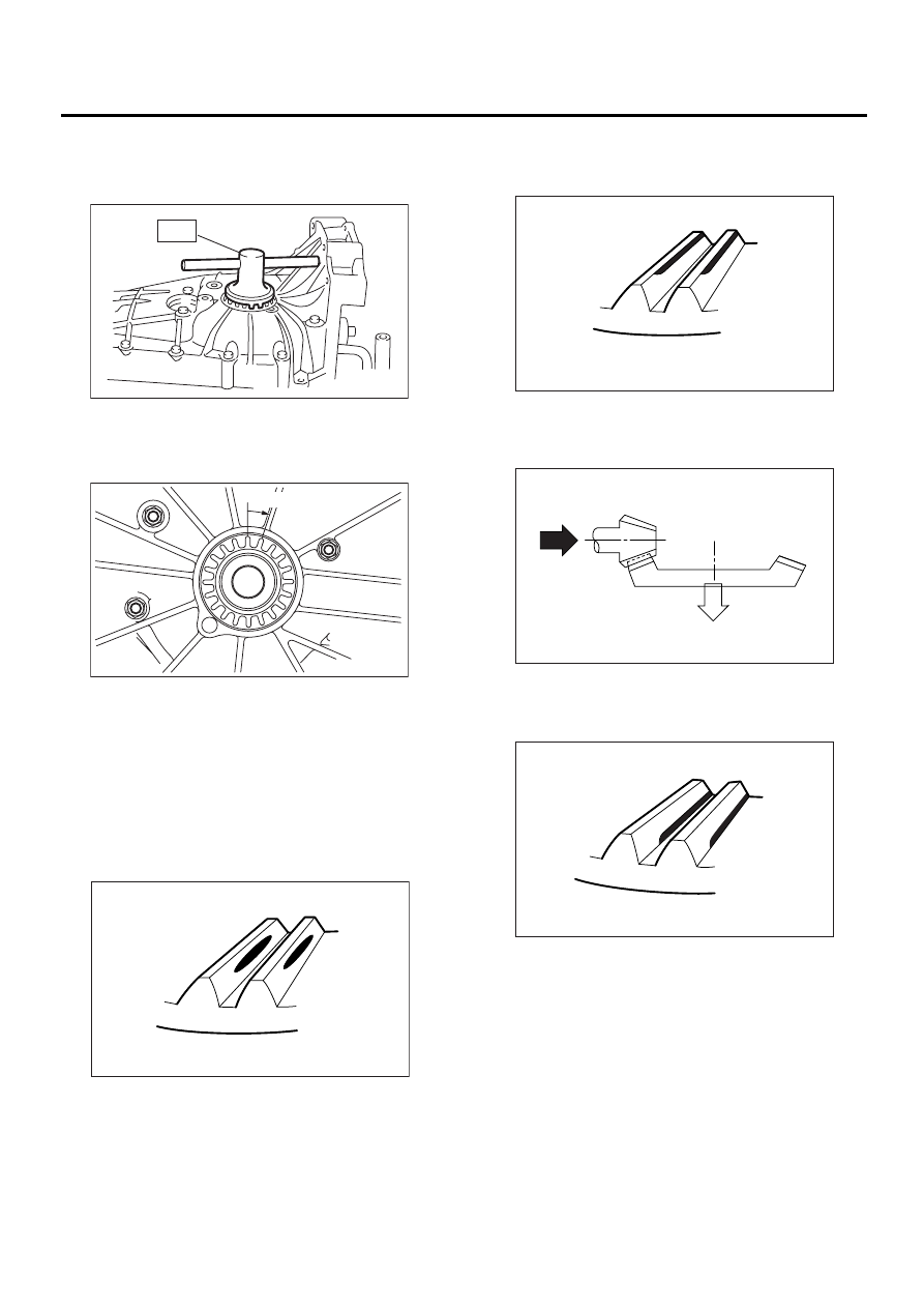
3. TOOTH CONTACT OF HYPOID GEAR
Check tooth contact of hypoid gear as follows: Ap-
ply a uniform thin coat of red lead on both tooth sur-
faces of 3 or 4 teeth of the hypoid gear. Move the
hypoid gear back and forth by turning the transmis-
sion main shaft until a definite contact pattern is de-
veloped on hypoid gear, and judge whether face
contact is correct. If it is inaccurate, make adjust-
ment. <Ref. to MT-100, ADJUSTMENT, Front Dif-
ferential Assembly.>
• Tooth contact is correct.
F: ADJUSTMENT
1. BEVEL PINION GEAR BACKLASH
1) Disassemble the front differential. <Ref. to MT-
95, REMOVAL, Front Differential Assembly.>
2) Select a different washer from the table and in-
stall.
3) Adjust until the specified value is obtained.
Standard backlash:
0.13 — 0.18 mm (0.0051 — 0.0071 in)
MT-00285
ST1
ST2
MT-00293
ST3
ST2
ST1
(A) Toe
(B) Coast side
(C) Heel
(D) Drive side
Washer
Part No.
Thickness mm (in)
803038021
0.925 — 0.950
(0.0364 — 0.0374)
803038022
0.975 — 1.000
(0.0384 — 0.0394)
803038023
1.025 — 1.050
(0.0404 — 0.0413)
MT-00294
( B )
( A )
( C )
( D )
MT-101
MANUAL TRANSMISSION AND DIFFERENTIAL
FRONT DIFFERENTIAL ASSEMBLY
2. HYPOID GEAR BACKLASH
Adjust backlash by turning holder in right side case.
ST
499787000
WRENCH ASSY
NOTE:
Each time holder rotates one tooth, backlash
changes by 0.05 mm (0.020 in).
3. TOOTH CONTACT OF HYPOID GEAR
Adjust until the teeth contact is correct.
Check and adjust the teeth contact with following
table.
• Tooth contact
Checking item: Tooth contact pattern is slightly
shifted toward to toe side under no-load
rotation. [When loaded, contact pattern moves
toward heel.]
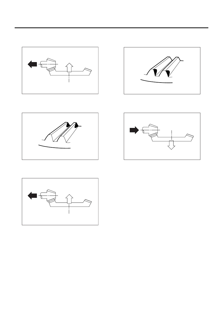
• Face contact
Checking item: Backlash is too large.
Contact pattern
Corrective action: Decrease thickness of drive pin-
ion adjusting shim in order to bring drive pinion
close to driven gear.
• Flank contact
Checking item: Backlash is too small.
Contact pattern
(A) Toe side
(B) Heel side
MT-00176
ST
MT-00296
0.05 mm (0.020 in)
AT-00207
(A)
(B)
AT-00208
AT-00212
AT-00209
MT-102
MANUAL TRANSMISSION AND DIFFERENTIAL
FRONT DIFFERENTIAL ASSEMBLY
Corrective action: Increase thickness of drive pin-
ion adjusting shim in order to move drive pinion
away from driven gear.
• Toe contact (Inside end contact)
Checking item: Contact areas is small.
Contact pattern
Corrective action: Increase thickness of drive pin-
ion adjusting shim in order to bring drive pinion
close to driven gear.
• Heel contact (Outside end contact)
Checking item: Contact areas is small.
Contact pattern
Corrective action: Reduce thickness of drive pinion
adjusting shim in order to move drive pinion away
from driven gear.
AT-00213
AT-00210
AT-00213
AT-00211
AT-00212
MT-103
MANUAL TRANSMISSION AND DIFFERENTIAL
SPEEDOMETER GEAR
20.Speedometer Gear
A: REMOVAL
1) Remove the manual transmission assembly
from vehicle. <Ref. to MT-32, REMOVAL, Manual
Transmission Assembly.>
2) Remove back-up light switch and neutral posi-
tion switch. <Ref. to MT-42, REMOVAL, Switches
and Harness.>
3) Remove transfer case with extension case as-
sembly. <Ref. to MT-47, REMOVAL, Transfer
Case and Extension Case Assembly.>
4) Remove transmission case. <Ref. to MT-59, RE-
MOVAL, Transmission Case.>
5) Remove vehicle speed sensor. <Ref. to MT-45,
REMOVAL, Vehicle Speed Sensor.>
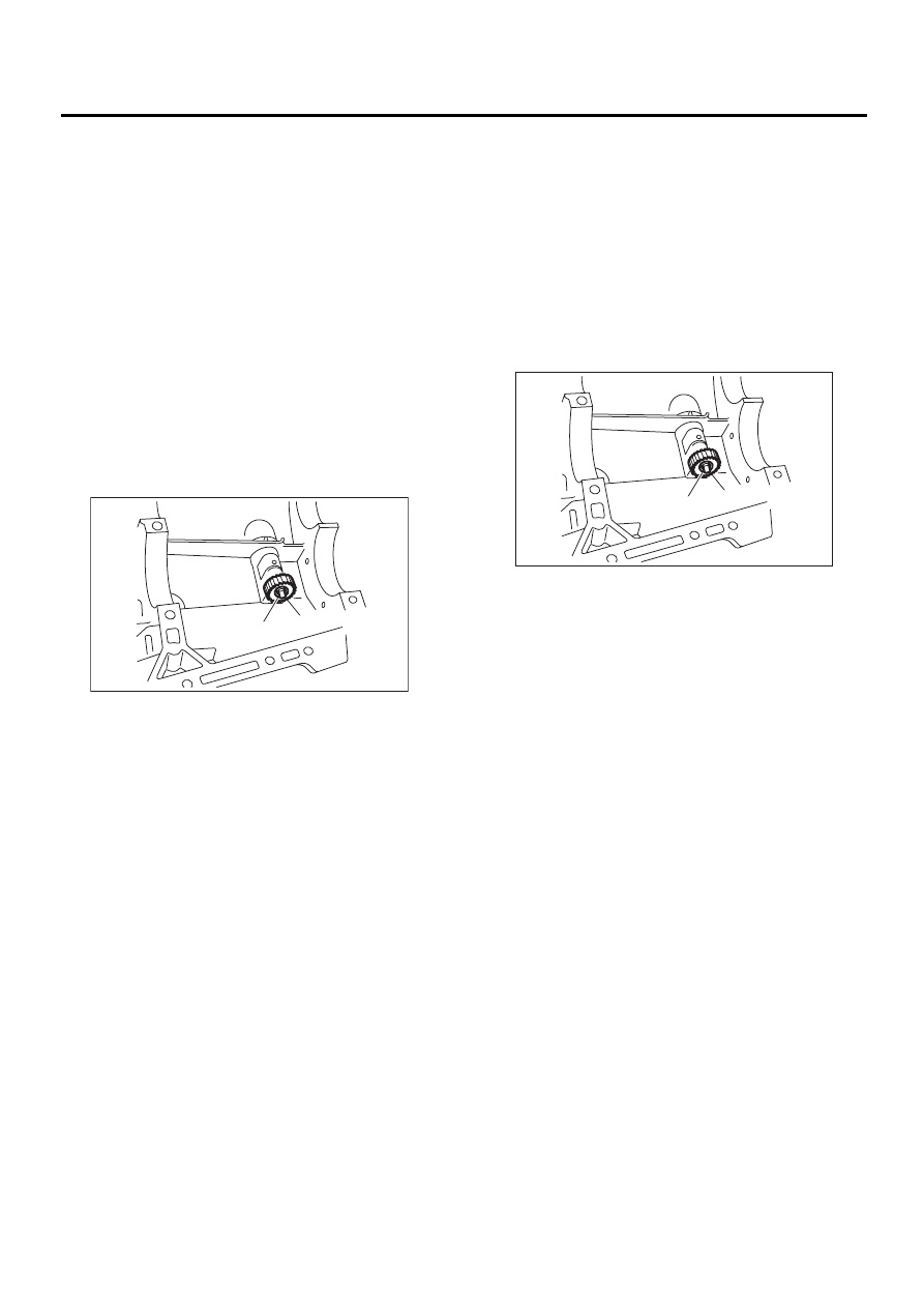
6) Remove outer snap ring and pull out speedome-
ter driven gear. Next, remove oil seal, speedometer
shaft and washer.
B: INSTALLATION
1) Install washer and speedometer shaft, and press
fit oil seal with ST.
NOTE:
Use new oil seal, if it has been removed.
ST
899824100 or 499827000 PRESS
2) Install vehicle speed sensor. <Ref. to MT-45, IN-
STALLATION, Vehicle Speed Sensor.>
3) Install speedometer driven gear and snap ring.
NOTE:
Use new snap ring, if it has been removed.
4) Install transmission case. <Ref. to MT-61, IN-
STALLATION, Transmission Case.>
5) Install transfer case with extension case assem-
bly. <Ref. to MT-47, INSTALLATION, Transfer
Case and Extension Case Assembly.>
6) Install back-up light switch and neutral position
switch. <Ref. to MT-43, INSTALLATION, Switches
and Harness.>
7) Install the manual transmission assembly to ve-
hicle. <Ref. to MT-35, INSTALLATION, Manual
Transmission Assembly.>
C: INSPECTION
Check the speedometer gear, oil seal and speed-
ometer shaft for damage. Replace if damaged.
(A) Outer snap ring
(B) Speedometer driven gear
MT-00301
( B )
( A )
(A) Outer snap ring
(B) Speedometer driven gear
MT-00301
( B )
( A )
Нет комментариевНе стесняйтесь поделиться с нами вашим ценным мнением.
Текст