Subaru Legacy III (2000-2003 year). Service manual — part 631
MT-92
MANUAL TRANSMISSION AND DIFFERENTIAL
DRIVE PINION SHAFT ASSEMBLY
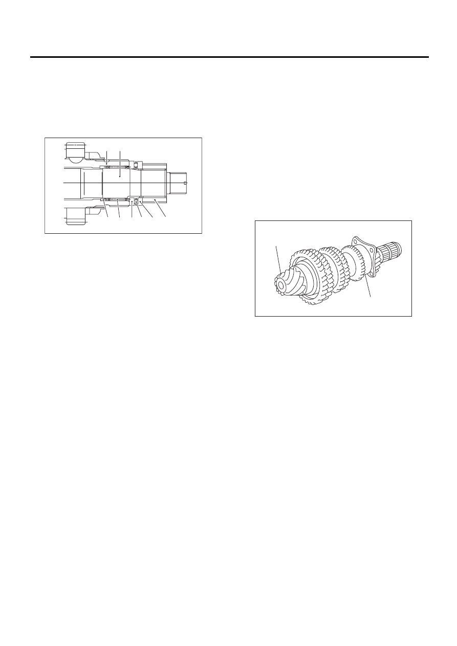
15) Install drive pinion collar, needle bearing, ad-
justing washer No. 2, thrust bearing, adjusting
washer No. 1 and differential bevel gear sleeve in
that order.
NOTE:
Be careful because spacer must be installed in
proper direction.
E: INSPECTION
Disassembled parts should be washed clean first
and then inspected carefully.
1) Bearings
Replace bearings in the following cases:
• Bearings whose balls, outer races and inner rac-
es are broken or rusty.
• Worn bearings
• Bearings that fail to turn smoothly or make ab-
normal noise when turned after gear oil lubrication.
• The ball bearing on the rear side of the drive pin-
ion shaft should be checked for smooth rotation be-
fore the drive pinion assembly is disassembled. In
this case, because a preload is working on the
bearing, its rotation feels like it is slightly dragging
unlike the other bearings.
• Bearings having other defects
2) Bushing (each gear)
Replace the bushing in the following cases:
• When the sliding surface is damaged or abnor-
mally worn.
• When the inner wall is abnormally worn.
3) Gears
• Replace gears with new ones if their tooth sur-
faces are broken, damaged, or excessively worn.
• Correct or replace if the cone that contacts the
baulk ring is rough or damaged.
• Correct or replace if the inner surface or end face
is damaged.
(A) Driven shaft
(B) Drive shaft
(C) Drive pinion collar
(D) Needle bearing (25
×
30
×
20)
(E) Washer No. 2 (25
×
36
×
4)
(F) Thrust bearing (25
×
37.5
×
3)
(G) Washer No. 1 (25
×
36
×
t)
(H) Differential bevel gear sleeve
MT-00263
( B )
( A )
( C )( D ) ( E ) ( F )( G ) ( H )
(A) Drive pinion shaft
(B) Ball bearing
MT-00264
( B )
( A )
MT-93
MANUAL TRANSMISSION AND DIFFERENTIAL
DRIVE PINION SHAFT ASSEMBLY
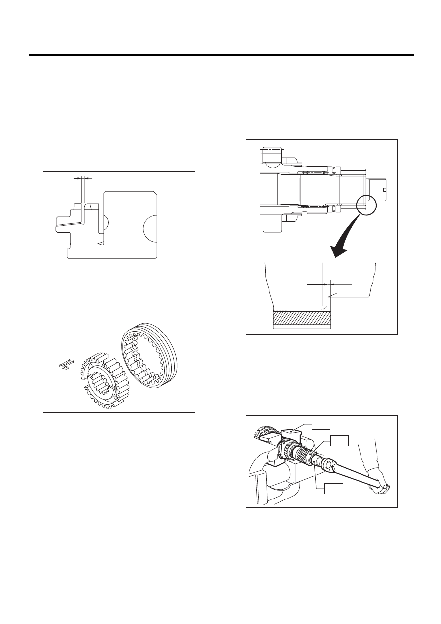
4) Baulk ring
Replace the ring in the following cases:
• When the inner surface and end face are dam-
aged.
• When the ring inner surface is abnormally or par-
tially worn down.
• If the gap between the end faces of the ring and
the gear splined part is excessively small when the
ring is pressed against the cone.
Clearance (A):
0.5 — 1.0 mm (0.020 — 0.040 in)
• When the contact surface of the synchronizer
ring insert is scored or abnormally worn down.
5) Shifting insert key
Replace the insert if deformed, excessively worn,
or defective in any way.
6) Oil seal
Replace the oil seal if the lip is deformed, hard-
ened, damaged, worn, or defective in any way.
7) O-ring
Replace the O-ring if the sealing face is deformed,
hardened, damaged, worn, or defective in any
way.
F: ADJUSTMENT
1. THRUST BEARING PRELOAD
1) After completing the preceding steps 1) through
3), select adjusting washer No. 1 so that dimension
(H) is zero through visual check. Position washer
(18.3
×
30
×
4) and lock washer (18
×
30
×
2) and in-
stall lock nut (18
×
13.5).
2) Using ST1, ST2 and ST3, tighten lock nut to the
specified torque.
ST1
899884100
HOLDER
ST2
498427100
STOPPER
ST3
899988608
SOCKET WRENCH (27)
Tightening torque:
120 N·m (12.2 kgf-m, 88.2 ft-lb)
MT-00265
( A )
MT-00208
MT-00267
“A”
( H )
MT-00268
ST1
ST2
ST3
MT-94
MANUAL TRANSMISSION AND DIFFERENTIAL
DRIVE PINION SHAFT ASSEMBLY
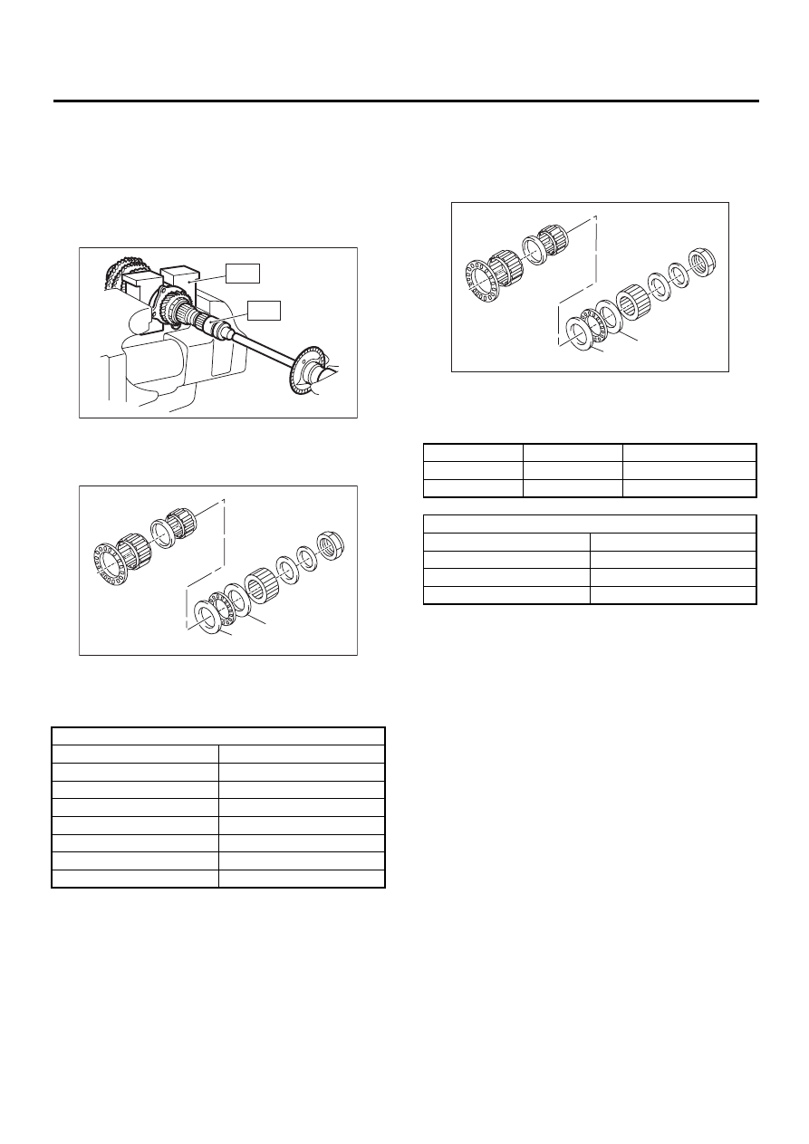
3) After removing ST2, measure starting torque us-
ing torque driver.
ST1
899884100
HOLDER
ST3
899988608
SOCKET WRENCH (27)
Starting torque:
0.3 —
0.8 N·m (0.03 —
0.08 kgf-m, 0.2 —
0.6
ft-lb)
4) If starting torque is not within specified limit, se-
lect new adjusting washer No. 1 and recheck start-
ing torque.
5) If specified starting torque range cannot be ob-
tained when a No. 1 adjusting washer is used, then
select a suitable No. 2 adjusting washer from those
listed in the following table. Repeat steps 1)
through 4) to adjust starting torque.
6) Recheck that starting torque is within specified
range, then clinch lock nut at four positions.
(A) Adjusting washer No. 1
(B) Adjusting washer No. 2
Adjusting washer No. 1
Part No.
Thickness mm (in)
803025051
3.925 (0.1545)
803025052
3.950 (0.1555)
803025053
3.975 (0.1565)
803025054
4.000 (0.1575)
803025055
4.025 (0.1585)
803025056
4.050 (0.1594)
803025057
4.075 (0.1604)
MT-00269
ST1
ST3
MT-00270
( A )
( B )
(A) Adjusting washer No. 1
(B) Adjusting washer No. 2
Starting torque
Dimension H
Washer No. 2
Low
Small
Select thicker one.
High
Large
Select thinner one.
Adjusting washer No. 2
Part No.
Thickness mm (in)
803025059
3.850 (0.1516)
803025054
4.000 (0.1575)
803025058
4.150 (0.1634)
MT-00270
( A )
( B )
MT-95
MANUAL TRANSMISSION AND DIFFERENTIAL
FRONT DIFFERENTIAL ASSEMBLY
19.Front Differential Assembly
A: REMOVAL
1) Remove the manual transmission assembly
from vehicle. <Ref. to MT-32, REMOVAL, Manual
Transmission Assembly.>
2) Remove transfer case with extension case as-
sembly. <Ref. to MT-47, REMOVAL, Transfer
Case and Extension Case Assembly.>
3) Remove transmission case. <Ref. to MT-59, RE-
MOVAL, Transmission Case.>
4) Removes drive pinion shaft assembly. Remove
transfer case with extension case assembly. <Ref.
to MT-87, REMOVAL, Drive Pinion Shaft Assem-
bly.>
5) Remove main shaft assembly.
Single-range model:
<Ref. to MT-66, REMOVAL, Main Shaft Assembly
for Single-Range.>
Dual-range model:
<Ref. to MT-74, REMOVAL, Main Shaft Assembly
for Dual-Range.>
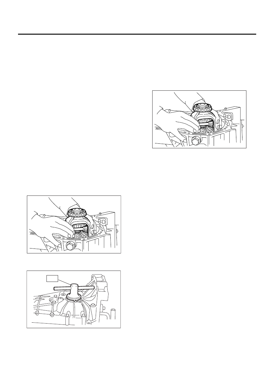
6) Remove differential assembly.
NOTE:
• Be careful not to confuse right and left roller
bearing outer races.
• Be careful not to damage retainer oil seal.
7) Remove differential side retainers using ST.
ST
499787000
WRENCH ASSY
8) Remove side bearing outer race from transmis-
sion case.
B: INSTALLATION
1) Install differential side retainers using ST.
ST
499787000
WRENCH ASSY
2) Install differential assembly.
NOTE:
• Be careful not to fold the sealing lip of oil seal.
• Wrap the left and right splines sections of axle
shaft with vinyl tape to prevent scratches.
3) Install main shaft assembly.
Single-range model:
<Ref. to MT-66, INSTALLATION, Main Shaft As-
sembly for Single-Range.>
Dual-range:
<Ref. to MT-74, INSTALLATION, Main Shaft As-
sembly for Dual-Range.>
4) Install drive pinion assembly. <Ref. to MT-87,
INSTALLATION, Drive Pinion Shaft Assembly.>
5) Install transmission case. <Ref. to MT-61, IN-
STALLATION, Transmission Case.>
6) Install transfer case with extension case assem-
bly. <Ref. to MT-47, INSTALLATION, Transfer
Case and Extension Case Assembly.>
7) Install the manual transmission assembly to ve-
hicle. <Ref. to MT-35, INSTALLATION, Manual
Transmission Assembly.>
MT-00162
MT-00176
ST
MT-00162
Нет комментариевНе стесняйтесь поделиться с нами вашим ценным мнением.
Текст